Dispersion compensation device
- Summary
- Abstract
- Description
- Claims
- Application Information
AI Technical Summary
Benefits of technology
Problems solved by technology
Method used
Image
Examples
example 1
(1) Modified Example 1 of the Photonic Crystal Layer
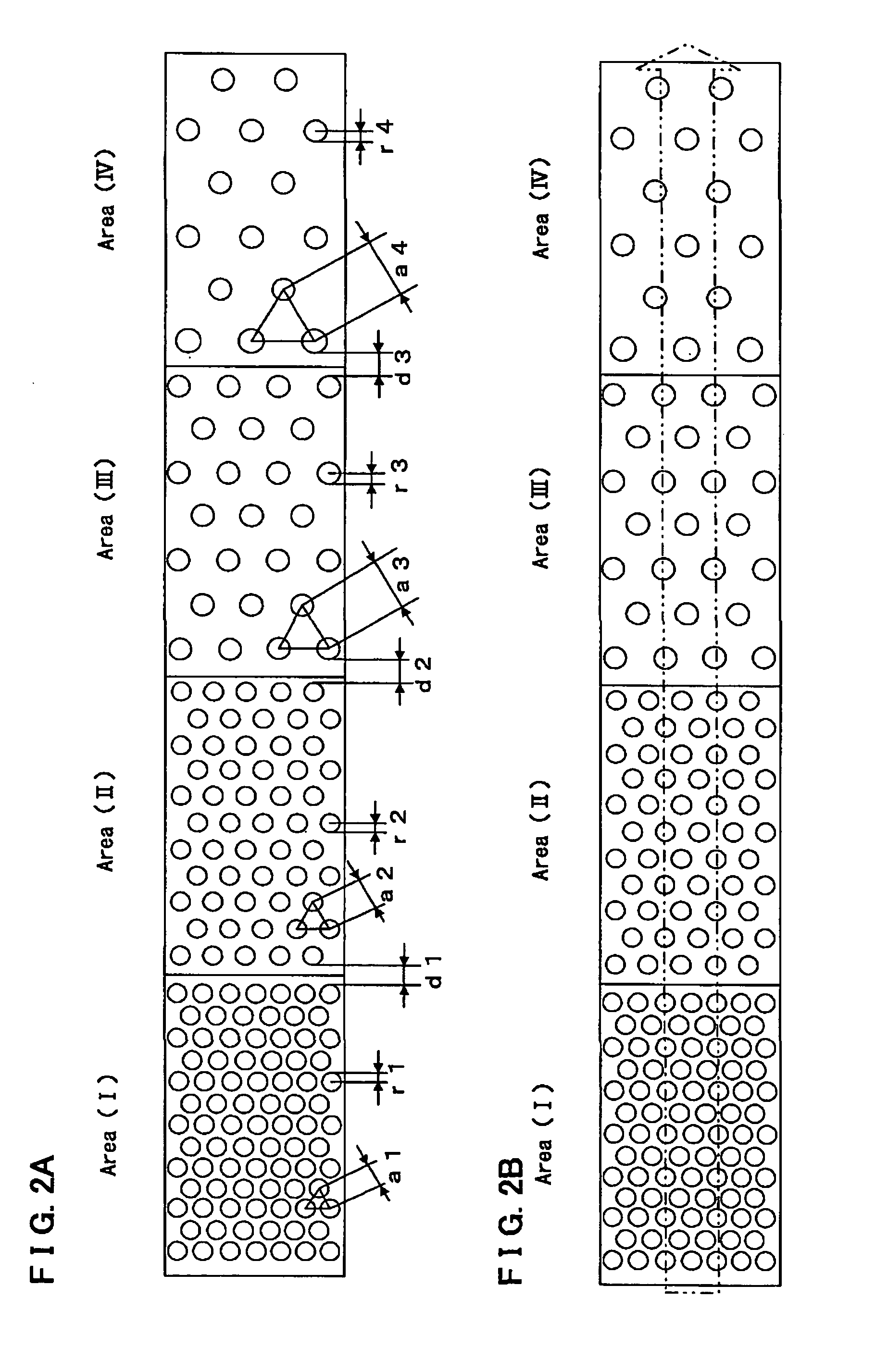
[0128] A modified configuration example of the photonic crystal layer 4 is described with reference to FIGS. 5A, 5B.
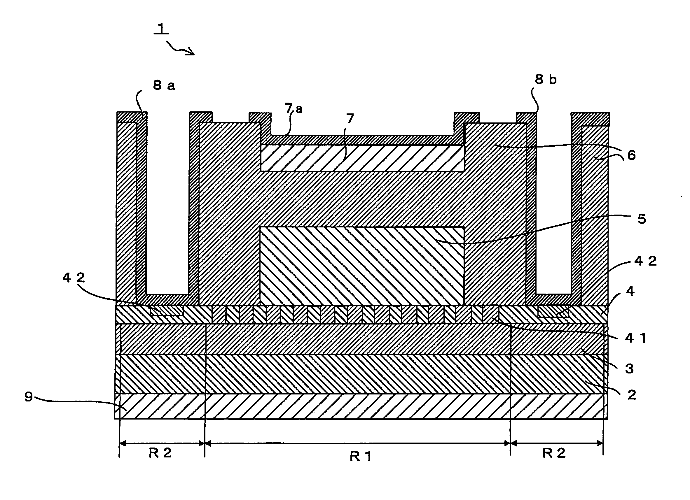
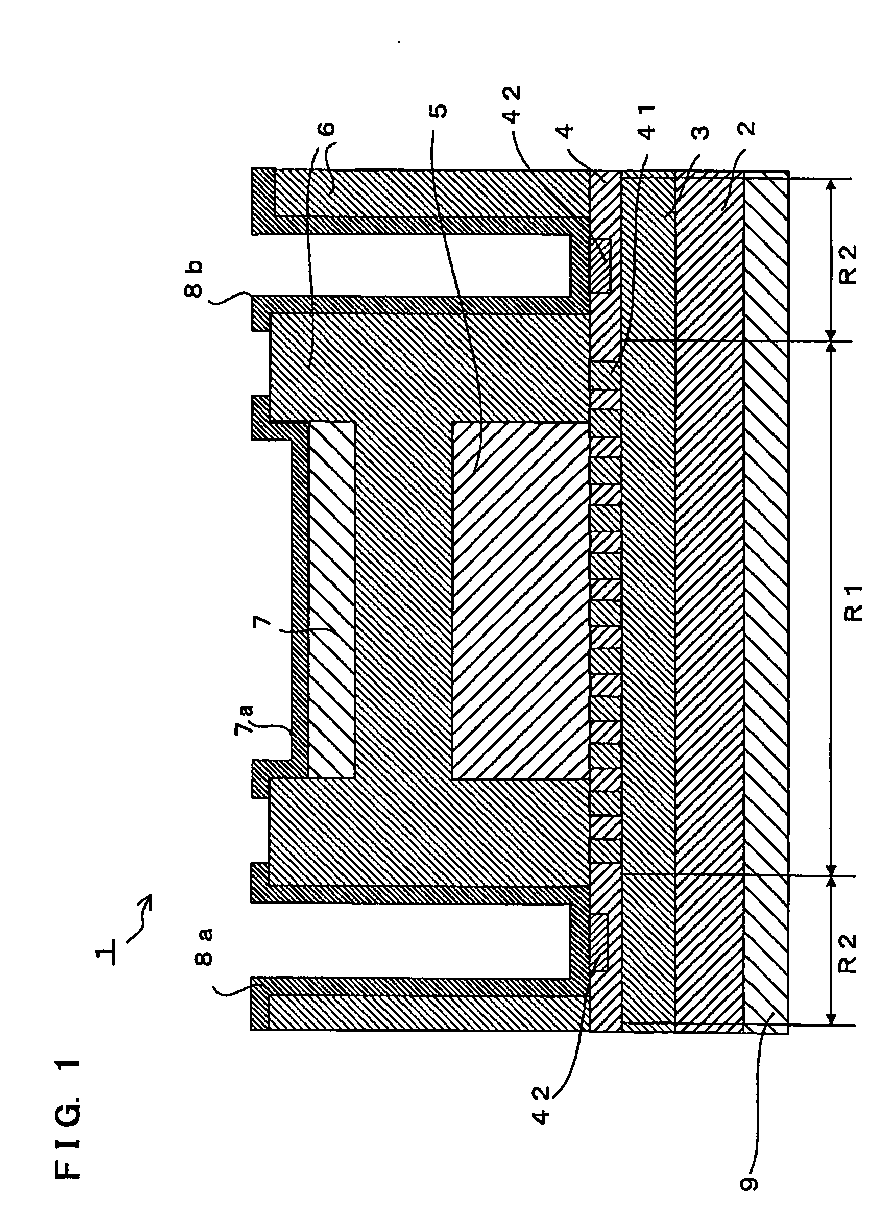
[0129] In the above described embodiment, the photonic crystal layer 4 is composed of the photonic crystal region R1 and extended regions R2, the photonic crystal region R1 being prepared by providing a plural number of plane-shaped holes 41 to the matrix material which is made of Si, and then filling up the holes 41 with SiO2 film of which dielectric constant is different from that of the matrix material, and the extended regions being located at both sides of the photonic crystal region R1 and being not provided with the hole 41. In this modified example, further by providing the barrier regions to inhibit or to restrain the propagation of the light and which are formed by a material the refractive index of which is smaller than Si at both side of the photonic crystal region R1, it is possible to transmit the light...
example 2
(2) Modified Example 2 of the Photonic Crystal Layer
[0134] Another modified configuration example of the photonic crystal layer 4 is described with reference to FIG. 6. In this example, the barrier areas as mentioned above can be realized by forming holes 41 in a different condition from that of above mentioned embodiment in the photonic crystal area R1.
[0135]FIG. 6 is an illustrative view for another modified construction example of the photonic crystal layer 4 which has holes 41 formed in the photonic crystal region R1 with a modified condition.
[0136] An interval (pitch) between holes 41 in each area is described using FIG. 6. Incidentally, we suppose that we explain the photonic crystal where the photonic band region is laid on the area (I) or area (II) as the lower-branch photonic band region.
[0137] Assuming that the interval (pitch) between holes 41 in the photonic crystal region R1 is aR1, the interval (pitch) between holes 41 in the barrier region is aR2, the center-to-cen...
PUM
 Abstract
Description
Claims
Application Information
 - R&D
- Intellectual Property
- Life Sciences
- Materials
- Tech Scout
- Unparalleled Data Quality
- Higher Quality Content
- 60% Fewer Hallucinations
Browse by: Latest US Patents, China's latest patents, Technical Efficacy Thesaurus, Application Domain, Technology Topic, Popular Technical Reports.
© 2025 PatSnap. All rights reserved.Legal|Privacy policy|Modern Slavery Act Transparency Statement|Sitemap|About US| Contact US: help@patsnap.com


