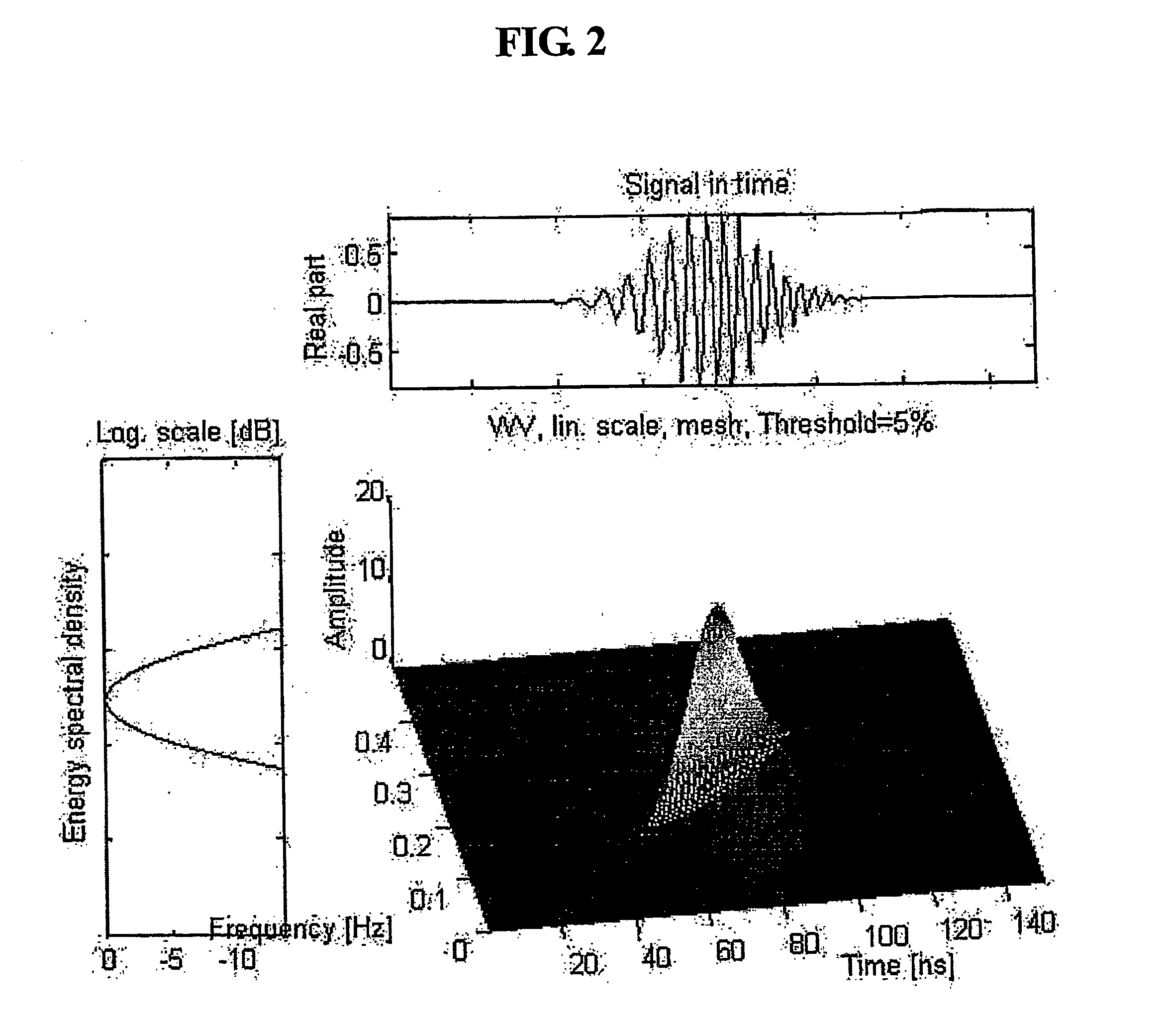
[0010] The new invention of methodology that we introduce is a joint time-frequency domain reflectometry (TFDR) technique can be characterized by its capability which captures many of the advantages of TDR and FDR mentioned previously. The reference signal is a chirp signal, which allows one to apply the RF power in the band of interest. To provide time localization, the chirp signal is multiplied by a Gaussian envelope in the time domain. The design of reference signal in time and frequency domain is the generalization of the contemporary reflectometry in time or frequency domain only time-frequency domain reflectometry can be characterized by time and frequency localization as a mixture of time domain reflectometry and frequency domain reflectometry. For example, under the conditions with no frequency sweep and the duration of the Gaussian envelope is very large, the reference signal of the time-frequency domain reflectometry takes on a pulse-like character reminiscent of the reference signal of TDR. Similarly, for a very small duration of the Gaussian envelope, the reference signal of the time-frequency domain reflectometry corresponds to the swept sinusoidal reference signal of FDR. Therefore, the time-frequency domain reflectometry scheme provides flexible application depending on the physical characteristics of the wire or cable under test. Note that the reference signals in TDR or FDR is constrained in time and frequency domain, respectively.
[0011] For the detection and localization, the time-frequency distributions of the reference signal and the reflected signals are calculated. Then these two time-frequency distributions are cross-correlated in the time-frequency domain. The peak in the time-frequency cross correlation function allows one to estimate an accurate round-trip propagation time and, hence, distance, as in classical TDR. However, for a higher-accuracy localization of the fault, the measured arrival time is compensated by the frequency offset of the reflected signal which can be converted into time information. This is an unique feature of the time-frequency domain reflectometry for the high-resolution detection and localization where the time and frequency information is treated simultaneously. Yet, the experiment is carried in an RF band of interest which is relevant for the particular wire / cable under test, as in FDR. The detailed description of the algorithm will be presented in next section.
[0012] Another object of the present invention is to provide time=frequency domain reflectometry apparatus having a wide spectrum of applications in geographic / resource surveys, material surface tests, radar / sonar purposes, communication network wirings, optical cable diagnoses, remote explorations, fluid pipe leakage detections, water gauges, etc. in addition to the conventional application in detecting and locating of faults in a conductor, with a new access method in reflectometry for processing signals that allows architecting an input signal and processing thereof in a time-frequency domain.
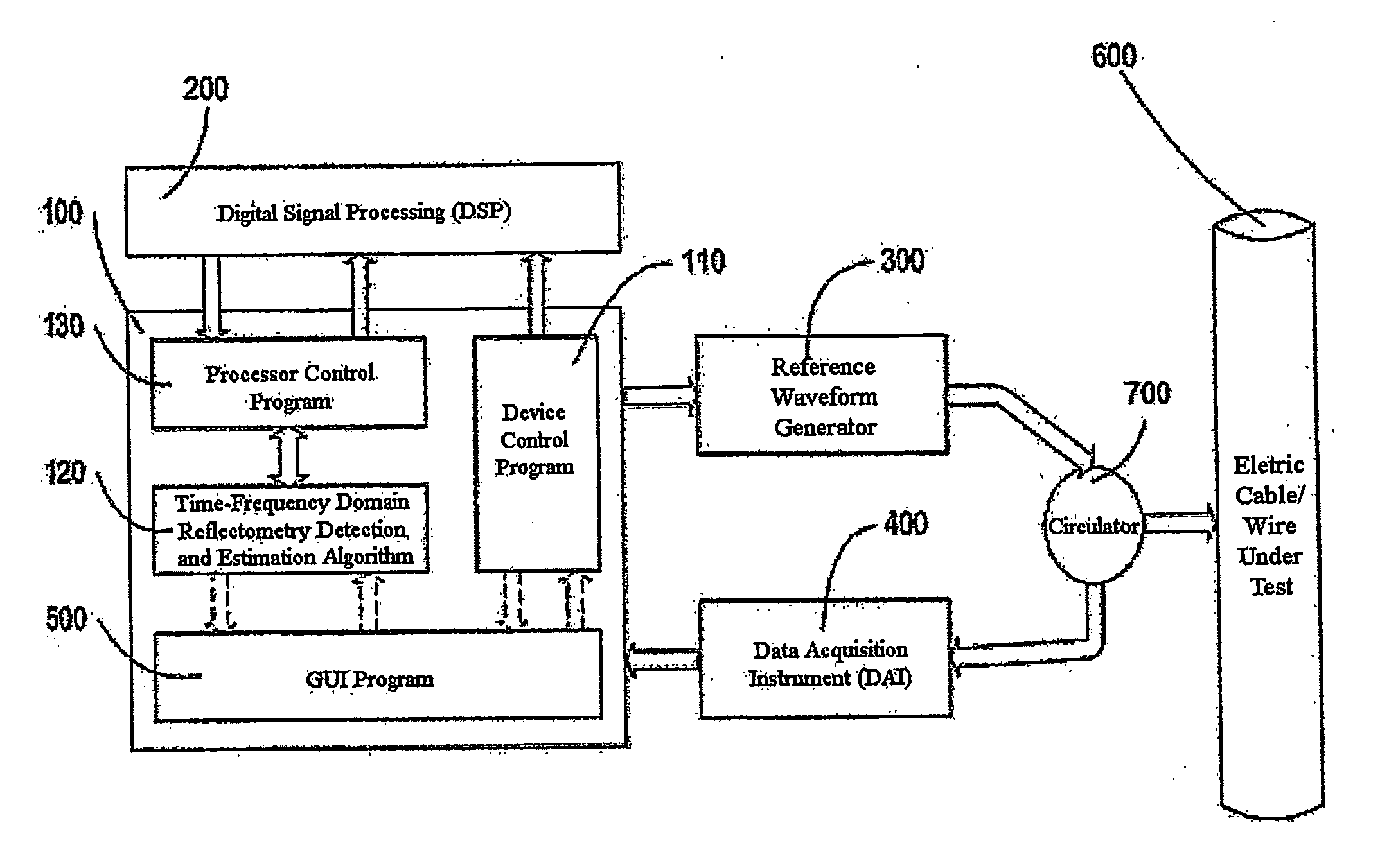
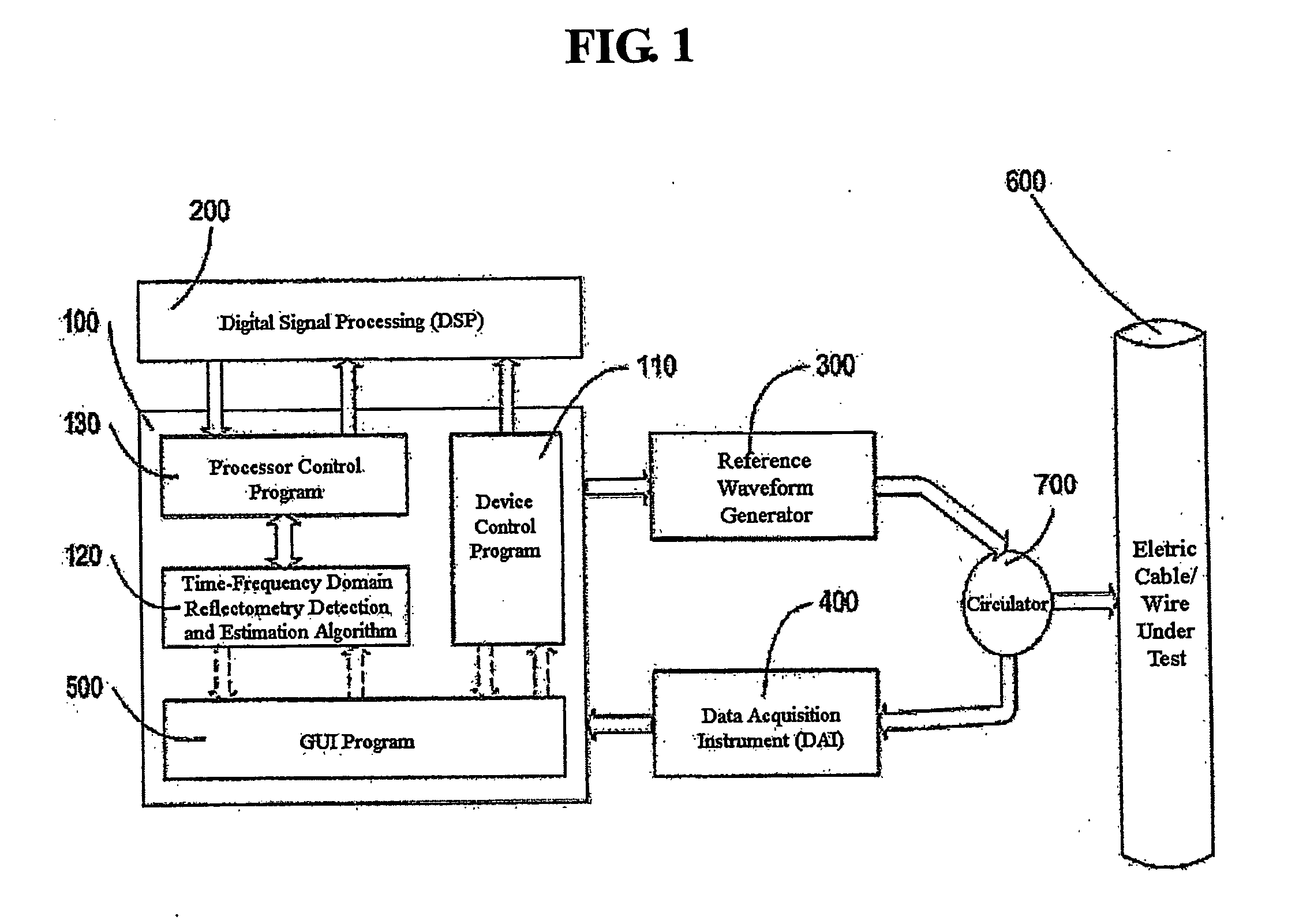
[0013] In order to achieve the above objects, a time-frequency domain reflectometry apparatus for detection and localization is composed of following components: a personal computer (PC) capable of performing main control program of a predetermined time-frequency domain reflectometry, including a device control program that controls control external instrumentation devices for the generation of the reference signal and acquisition of the reflected signs. The system consists of a circulator, the waveform generator and the data acquisition equipment which is connected to a computer with GPIB cable for automatic control of the instruments. The computer controls the waveform generator to produce the Gaussian envelope chirp signal which propagates into the target cable via the circulator. This reference signal is reflected at the fault location and back to the circulator. The circular redirects the reflected signal to the data acquisition equipment. The computer controls and synchronizes the waveform generator and data acquisition equipment, calculates the time-frequency distribution of the reference signal and reflected signals, and executes the time-frequency cross correlation algorithm.

