Exposure apparatus, exposure method, and method for producing device

a technology of exposure apparatus and exposure method, which is applied in the direction of photomechanical apparatus, printing, instruments, etc., can solve the problems of insufficient margin, inconvenience, and difficulty in matching the substrate surface with respect to the image plane of the projection optical system

Inactive Publication Date: 2006-05-11
NIKON CORP
View PDF49 Cites 22 Cited by
  • Summary
  • Abstract
  • Description
  • Claims
  • Application Information

AI Technical Summary

Benefits of technology

[0019] According to the present invention, the affinity for the liquid of the first surface area including the optical element disposed at the tip of the projection optical system is made higher than that of the second surface area disposed therearound. Accordingly, the liquid is stably arranged on the optical path for the exposure light beam owing to the first surface area. Further, the liquid is not spread with the wetting to the surroundings owing to the second surface area, and thus does not outflow to the outside. Therefore, the liquid can be stably arranged on the optical path for the exposure light beam even in the case of the full field exposure in which the substrate stands still with respect to the exposure light beam during the exposure as well as in the case of the scanning type exposure in which the substrate is moved with respect to the exposure light beam during the exposure.
[0024] According to the present invention, the condition, under which the liquid is maintained in at least the part of the space between the projection optical system (PL) and the substrate (P), is set so that the conditional expression described above is satisfied. Accordingly, no turbulence arises in the liquid. Therefore, it is possible to suppress any inconvenience which would be otherwise caused, for example, such that the pattern image to be projected onto the substrate is deteriorated due to the turbulence of the liquid.
[0029] According to the present invention, the liquid immersion state is controlled by various methods, and thus the liquid flows while forming the laminar flow in parallel to the scanning direction of the substrate during the exposure. Therefore, it is possible to avoid the deterioration of the pattern image to be projected onto the substrate. Further, no unnecessary vibration is generated, for example, in the projection optical system which makes contact with the liquid as well as in the wafer and the substrate stage which holds the wafer. The flow of the liquid can be made into the laminar flow, for example, by controlling the amount of supply (recovery) of the liquid by the liquid immersion unit, adjusting the structure of the liquid supply nozzle of the liquid immersion unit, and / or adjusting the velocity when the substrate is moved during the exposure.
[0035] According to the present invention, the liquid immersion unit is controlled such that the liquid is not supplied during the exposure for the substrate. Accordingly, the photosensitive material, which has been applied onto the substrate, is not damaged. It is possible to avoid the deterioration of the pattern to be formed on the substrate. Further, the positional relationship between the projection optical system and the substrate can be stably maintained in a desired state.
[0040] According to the present invention, the surface treatment is applied to the surface of the substrate depending on the affinity for the liquid before performing the liquid immersion exposure. Accordingly, the liquid can be maintained on the substrate in a state preferable for the liquid immersion exposure. For example, if the affinity for the liquid is too low, any inconvenience arises, for example, such that the liquid is exfoliated from the surface of the substrate, and / or any bubble is generated. On the other hand, if the affinity for the liquid is too high, any inconvenience arises in some cases, for example, such that the liquid is spread excessively while causing wetting on the substrate. On the contrary, when the appropriate surface treatment is applied to the substrate surface in consideration of the affinity for the liquid as in the exposure method of the present invention, then the liquid can be maintained in a desired state on the substrate, and it is possible to appropriately perform the recovery and the removal of the liquid on the substrate.

Problems solved by technology

If the depth of focus δ is too narrowed, it is difficult to match the substrate surface with respect to the image plane of the projection optical system.
It is feared that the margin is insufficient during the exposure operation.
An inconvenience arises such that the pattern image, which is to be transferred to the substrate, is deteriorated.
In other cases, the pattern image is deteriorated as well when any turbulence appears in the liquid flow when the exposure is performed while making the liquid to flow through the space between the projection optical system and the substrate.

Method used


Image

  • Exposure apparatus, exposure method, and method for producing device
  • Exposure apparatus, exposure method, and method for producing device
  • Exposure apparatus, exposure method, and method for producing device

Examples


second embodiment

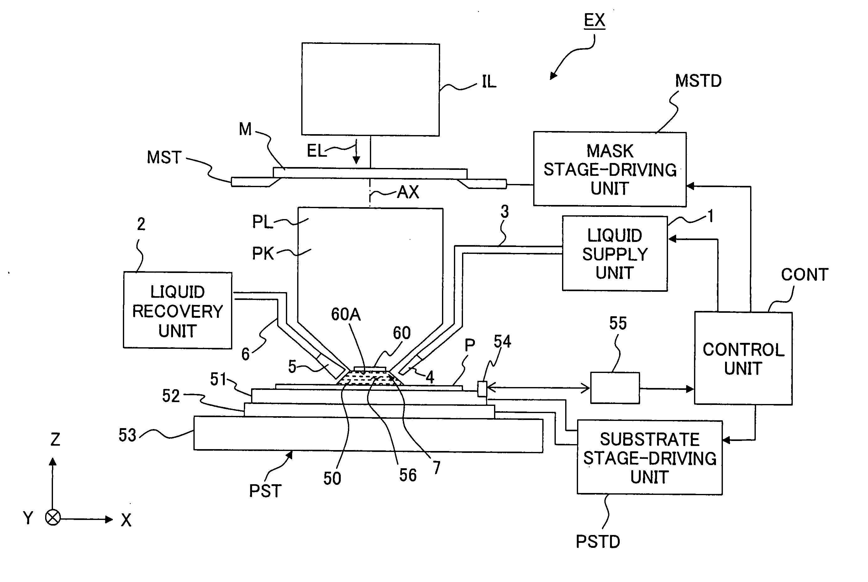
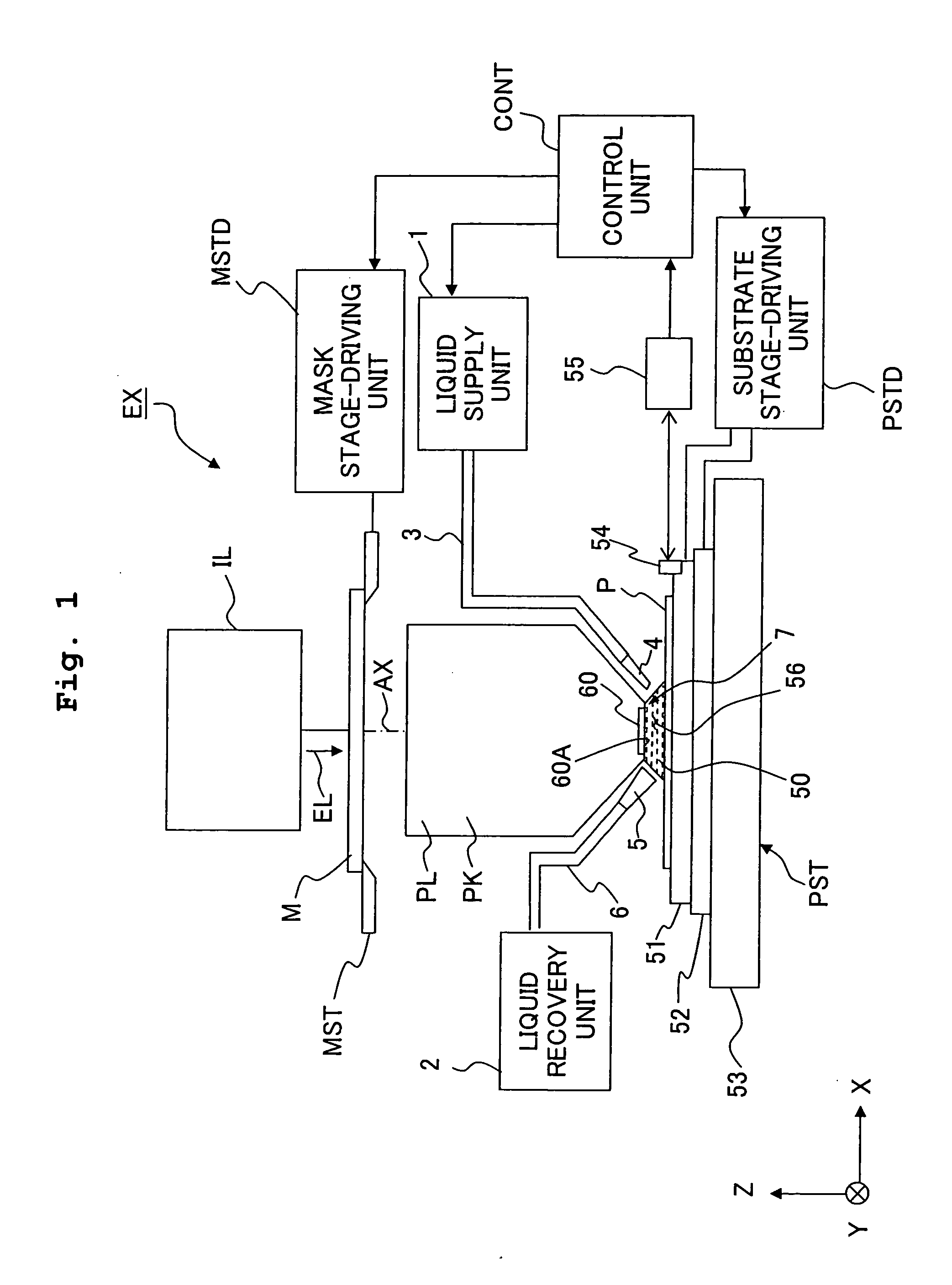
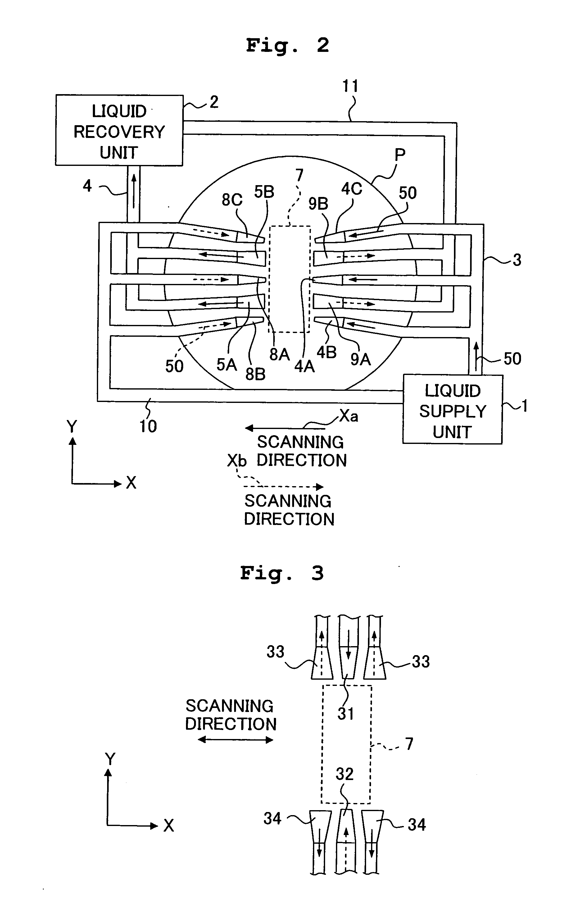
[0092] Next, an explanation will be made with reference to FIG. 7 about the present invention.

[0093] An exposure apparatus EX of this embodiment is designed such that the following conditional expression is satisfied provided that d represents a thickness of the liquid 50 between the lower surface 7A of the projection optical system PL and the surface of the substrate P (in this case, the spacing distance between the projection optical system PL and the substrate P), v represents a velocity of a flow of the liquid 50 between the projection optical system PL and the substrate P, ρ represents a density of the liquid 50, and μ represents a coefficient of viscosity of the liquid 50:

(v·d·ρ) / μ≦2,000  (3)

Accordingly, the liquid 50 flows as a laminar flow in the space 56. As for the liquid 50, it is also assumed that a plurality of different flow velocities v exist depending on the position in the liquid. However, it is enough that the maximum velocity Vmax thereof satisfies the expressi...


PUM

PropertyMeasurementUnit
refractive indexaaaaaaaaaa
wavelengthaaaaaaaaaa

Abstract

A liquid immersion photolithography system has an exposure system that exposes an exposure area on a substrate with electromagnetic radiation and includes a projection optical system. In addition, a liquid flow is provided between the projection optical system and the exposure area. Further, a member at one side of the projection optical system provides the liquid flow having a desired velocity profile when the liquid flow is present in the exposure area.

Description

CROSS-REFERENCE [0001] This is a Division of application Ser. No. 11 / 147,373 filed Jun. 8, 2005, which in turn is a Continuation of International Application No. PCT / JP03 / 015735 filed on Dec. 9, 2003 and that claims the conventional priority of Japanese patent Application No. 2002-357931 filed on Dec. 10, 2002. The disclosures of these applications are incorporated herein by reference in their entireties.BACKGROUND OF THE INVENTION [0002] 1. Field of the Invention [0003] The present invention relates to an exposure apparatus and an exposure method for performing the exposure with an image of a pattern projected by a projection optical system in a state in which at least a part of a space between the projection optical system and a substrate is filled with a liquid. The present invention also relates to a method for producing a device. [0004] 2. Description of the Related Art [0005] Semiconductor devices and liquid crystal display devices are produced by the so-called photolithograph...

Claims


Application Information

Patent Timeline
Patent Type & Authority Applications(United States)
IPC IPC(8): G03B27/42G03F7/20
CPCG03F7/2041G03F7/709G03F7/70341H01L21/0274
Inventor NAGASAKA, HIROYUKIMAGOME, NOBUTAKA
Owner NIKON CORP
Why Eureka
Try Eureka