Eureka AIR delivers breakthrough ideas for toughest innovation challenges, trusted by R&D personnel around the world.

Multi-port cable for removable ESD/EOD protection for electronic devices

a technology of electronic devices and multi-port cables, which is applied in the field of multi-port cables for esd/eod protection for electronic devices, can solve the problems of spurious discharge of static electricity, more sensitive to damage of thin sheet resistors, and buildup of electrostatic charges

Inactive Publication Date: 2006-05-11
IBM CORP
View PDF6 Cites 19 Cited by
  • Summary
  • Abstract
  • Description
  • Claims
  • Application Information

AI Technical Summary

Benefits of technology

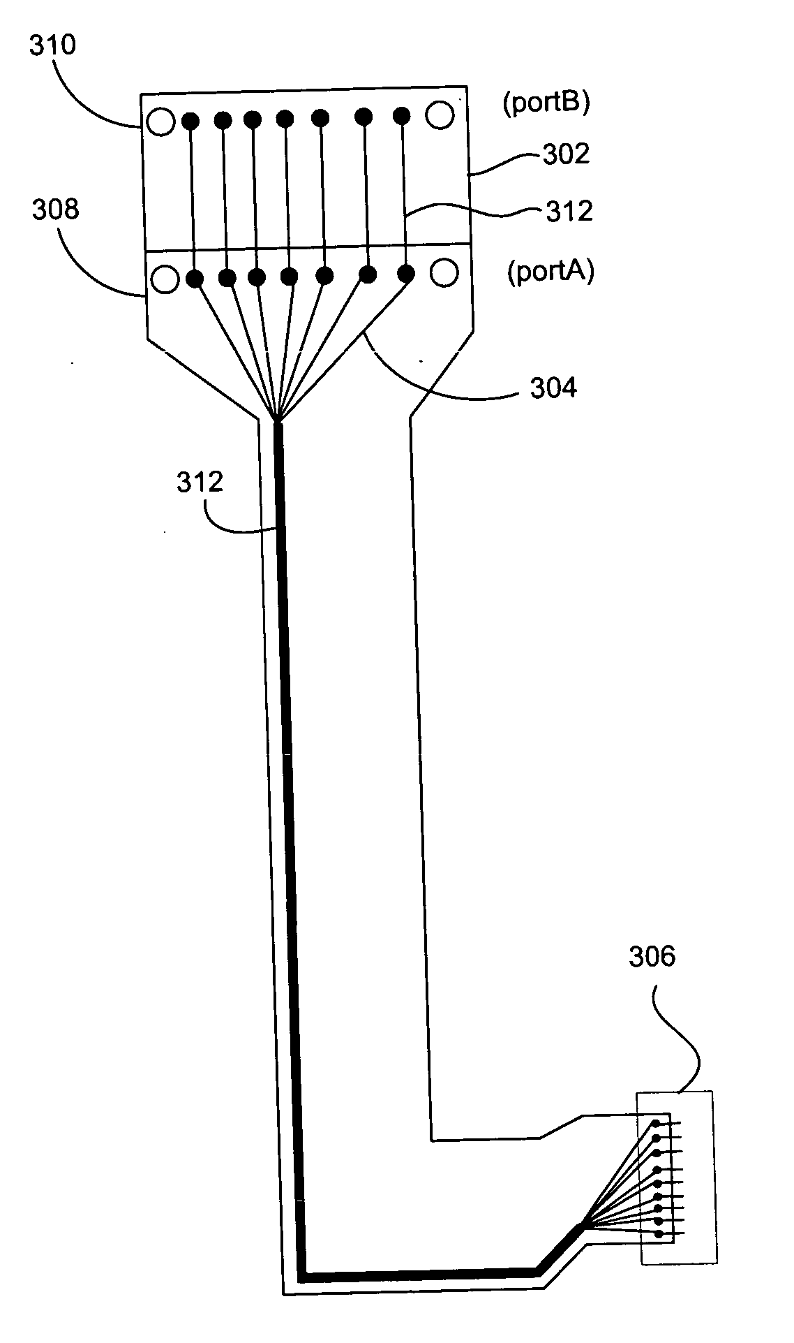
[0019] The present invention provides a mechanism for protecting an electronic device, e.g., MR elements, from ESD / EOS damage. The protective device includes a cable having leads coupled to the electronic device and a first port providing access to the leads. An extension has leads electrically coupled to the leads of the cable and a second port providing access to the leads of the extension. A shorting device is coupled to one of the ports thereby creating a short between both the leads of the extension and the leads of the cable.
[0020] The extension can be an integral part of the cable. For instance, the extension leads can be part of the initial cable fabrication and thus represent very little additional cost.
[0022] Preferably, the shorting device is detachably coupleable to one of the ports. The shorting device can be a wire mesh or wire sheet. The shorting device can also be an electrically conductive metal sheet. To enhance the protection afforded by the protective device, a grounding can be provided to electrically ground the shorting device. The grounding preferably includes a resistor having a high impedance to slowly dissipate any voltage differential between the cable leads, head, shorting connector, and the testing device.
[0023] To further enhance the protection afforded by the protective device, an outer surface of the cable and / or the extension can include an electrostatic dissipative material.

Problems solved by technology

The smaller the dimensions, the more sensitive the thin sheet resistors become to damage from spurious current or voltage spike.
A major problem that is encountered during manufacturing, handling and use of MR sheet resistors as magnetic recording transducers is the buildup of electrostatic charges on the various elements of a head or other objects which come into contact with the sensors, particularly sensors of the thin film type, and the accompanying spurious discharge of the static electricity thus generated.
These static charges may be discharged through the head causing excessive heating of the sensitive sensors which result in physical or magnetic damage to the sensors.
As described above, when a head is exposed to voltage or current inputs which are larger than that intended under normal operating conditions, the sensor and other parts of the head may be damaged.
This sensitivity to electrical damage is particularly severe for MR read sensors because of their relatively small physical size.
Discharge currents of tens of milliamps through such a small resistor can cause severe damage or complete destruction of the MR sensor.
The nature of the damage which may be experienced by an MR sensor varies significantly, including complete destruction of the sensor via melting and evaporation, oxidation of materials at the air bearing surface (ABS), generation of shorts via electrical breakdown, and milder forms of magnetic or physical damage in which the head performance may be degraded.
The large number of MR sensors in a tape drive and the requirement that all are functional, makes ESD loss due to a single element very expensive as the entire head must then be scrapped.
The problem with (1a)-(1c) is the cost of the permanent solution.
(1b) prohibits measuring the properties of the MR sensor until it is in the final device and a large amount of cost has gone into fabrication and assembly.
The problem with (2a) is that the device can not be tested during assembly without removing the short and subjecting the sensors to the potential of EOS / ESD damage.
The problem with (2b) is the substantial cost of the diodes.

Method used


Image

  • Multi-port cable for removable ESD/EOD protection for electronic devices
  • Multi-port cable for removable ESD/EOD protection for electronic devices
  • Multi-port cable for removable ESD/EOD protection for electronic devices

Examples


Embodiment Construction

[0041] The following description is the best embodiment presently contemplated for carrying out the present invention. This description is made for the purpose of illustrating the general principles of the present invention and is not meant to limit the inventive concepts claimed herein.

[0042] The present description discloses a protective cable and shorting system for protecting components of an electronic device from ESD and EOS damage. Although the invention is described as embodied for use with a magnetic tape storage system, the invention also applies to other electronic devices, including, e.g., magnetic recording systems and applications using a sensor to detect a magnetic field.

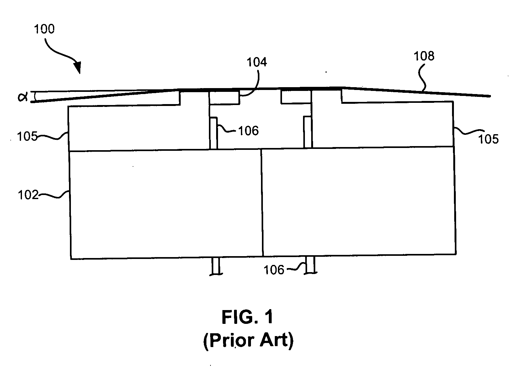
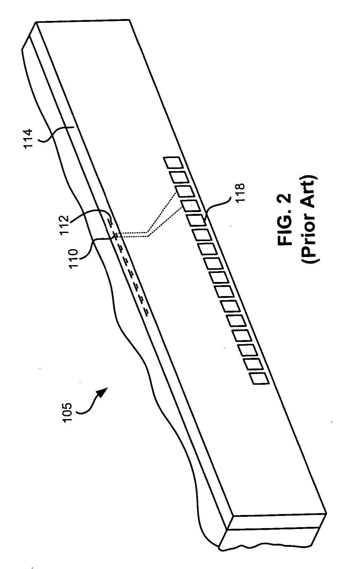
[0043] Prior art FIG. 1 illustrates a tape head in use. As shown, FIG. 1 illustrates a completed head for a read-while-write bidirectional linear tape drive. “Read-while-write” means that the read element follows behind the write element. This arrangement allows the data just written by the write el...


PUM

PropertyMeasurementUnit
heightaaaaaaaaaa
widthaaaaaaaaaa
widthaaaaaaaaaa

Abstract

A protective device for protecting an electronic device, e.g., MR head, from ESD / EOS damage includes a cable having leads coupled to the electronic device and a first port providing access to the leads. A second port with one-to-one electrical connection to each lead in the cable provides a second electrical access to the all leads. A shorting device is coupled to one of the ports thereby creating a short between both the leads of the extension and the leads of the cable. The other port is available for coupling to an external device, e.g., tester or end device while the short provides ESD / EOS protection.

Description

FIELD OF THE INVENTION [0001] The present invention relates to a device for protection from electrostatic discharge and electrical overstress, and more particularly, this invention relates to using a cable having multiple ports including a shortable port for protecting an electronic device from electrostatic discharge and electrical overstress. BACKGROUND OF THE INVENTION [0002] Magnetic head-based systems have been widely accepted in the computer industry as a cost-effective form of data storage. In a magnetic tape drive system, a magnetic tape containing a multiplicity of laterally positioned data tracks that extend along the length of the tape is drawn across a magnetic read / write transducer, referred to as a magnetic tape head. The magnetic tape heads can record and read data along the length of the magnetic tape surface as relative movement occurs between the heads and the tape. Because magnetic tape is a flexible media, its lateral position fluctuates as the tape is pulled at ...

Claims


Application Information

Patent Timeline
Patent Type & Authority Applications(United States)
IPC IPC(8): G11B5/33G11B5/127G11B21/16G11B5/48
CPCG11B5/40G11B5/455G11B33/1493
Inventor T
Owner IBM CORP
Why Eureka
Eureka Blog
Learn More