Internal Leakage Control and Venting for ABS Unit

a technology of internal leakage control and abs unit, which is applied in the direction of positive displacement liquid engine, piston pump, liquid fuel engine, etc., can solve the problems of inability to form two mutually isolated sub-units (motor and pump) and vehicle accidents with such conventional brake system. , to achieve the effect of simple arrangement and machining of the cavity

Inactive Publication Date: 2006-05-11
ROBERT BOSCH CORP
View PDF6 Cites 19 Cited by
  • Summary
  • Abstract
  • Description
  • Claims
  • Application Information

AI Technical Summary

Benefits of technology

[0012] An advantage of the present invention is that the location of the reservoir of the present invention prevents hydraulic fluid from entering the electric motor portion of the unit.
[0013] Another advantage is the simple arrangement and machining of the cavity with existing tooling. No reservoir cap or other extra parts are necessary.
[0014] A further advantage of the present invention is its applicability to a variety of existing hydraulic pump designs by minimal modification.

Problems solved by technology

However, the vehicles with such conventional brake systems may slip over a road in accordance with road surface conditions or variations in fluid pressure during a braking operation.
These units are typically sealed against the ingress of external moisture, thus, any fluid which leaks from the piston pumps is not readily removable from the unit.
Attempts to form such units as two mutually isolated sub-units (motor and pump) have not proven successful.
One problem is that internal heating which occurs during unit operation may create pressure differentials within the unit causing fluid to flow between the sub-units.
With such pumping sets there is also the problem that because of temperature variations between the interior of the electric motor and the space, in which the eccentric pump arrangement is situated, a (short-term) differential pressure may arise.
Conventional scaling methods (sealing rings, sealed bearings etc.) are too expensive and also do not prevent the hydraulic fluid from being dispersed into the environment.

Method used


Image

  • Internal Leakage Control and Venting for ABS Unit
  • Internal Leakage Control and Venting for ABS Unit
  • Internal Leakage Control and Venting for ABS Unit

Examples


Embodiment Construction

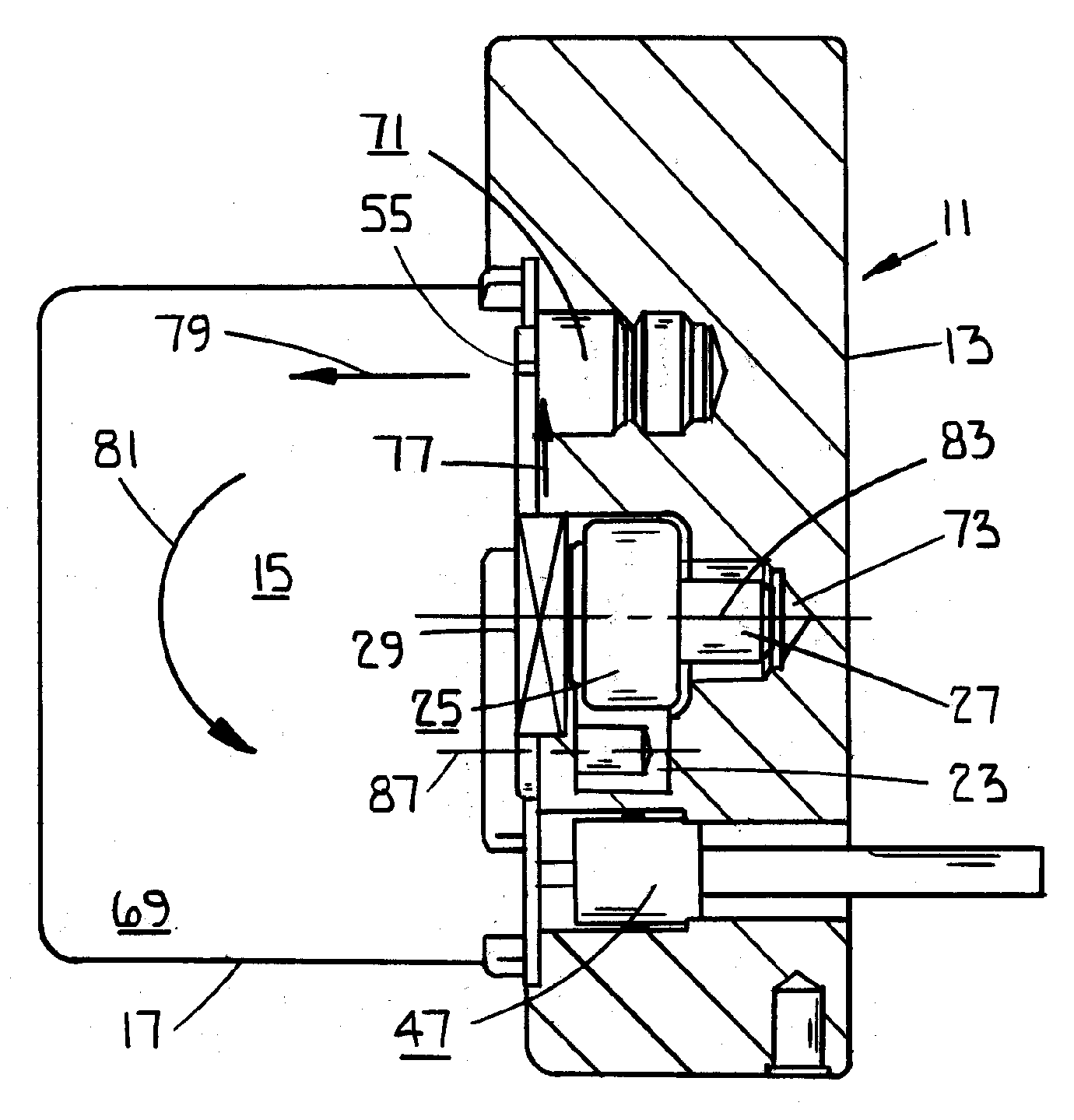
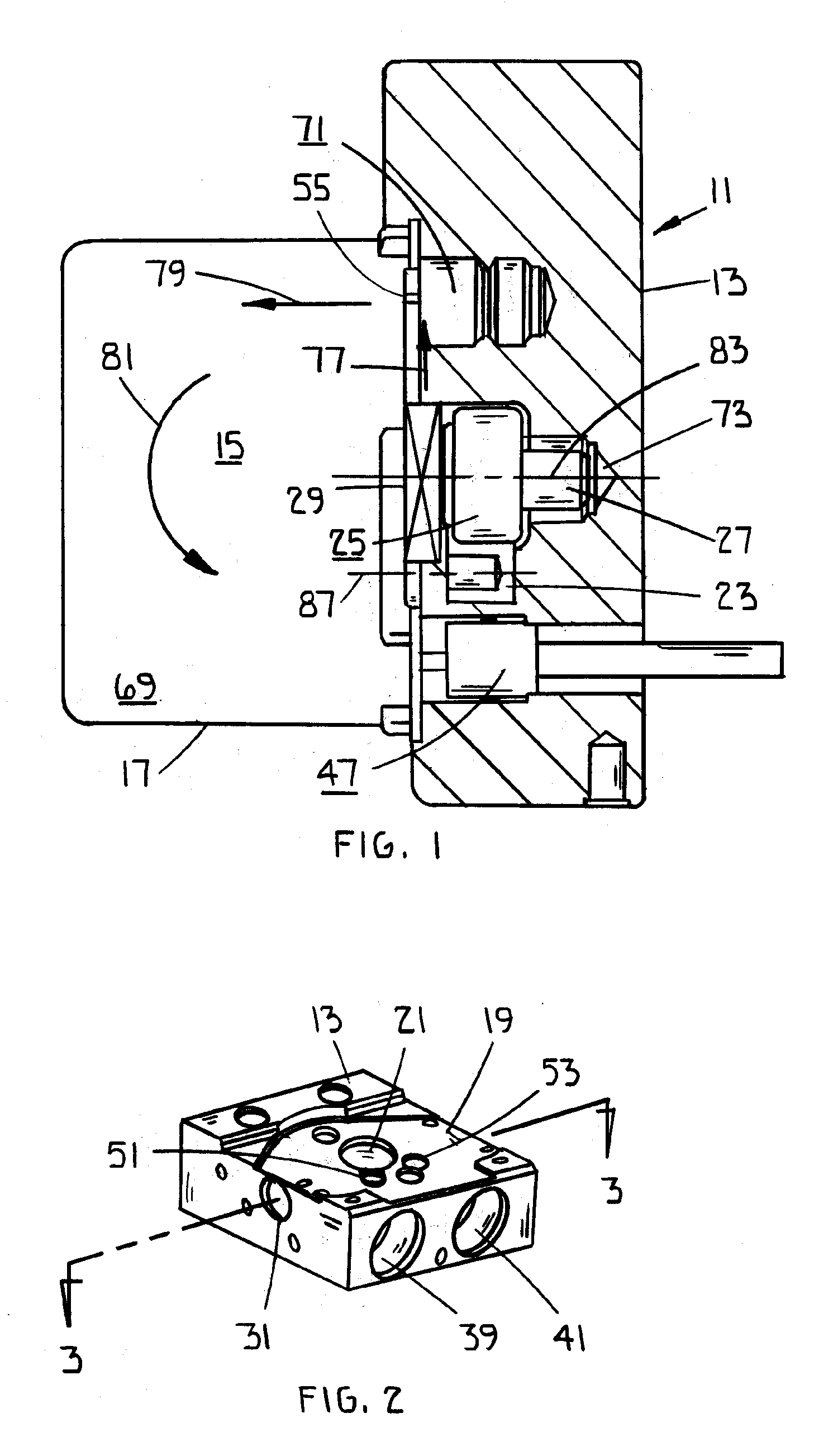
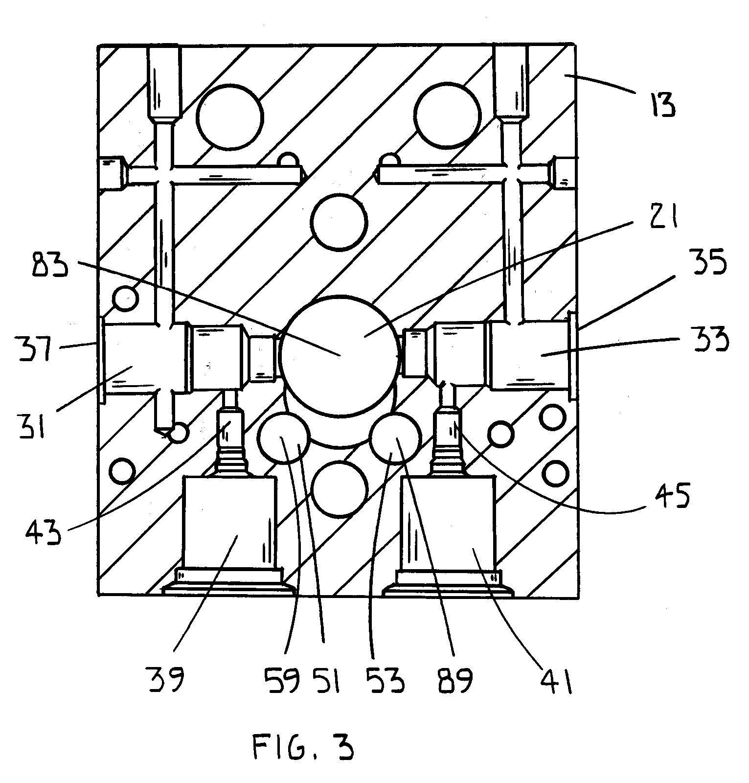
[0023] Referring now to the drawings and particularly to FIG. 1, there is shown a hydraulic unit 11 which includes a pump housing block 13 and, mounted against the housing block 13, a pump driving motor 15, having motor shaft 27 rotatable about axis 83. The motor is positioned within a motor enclosure or covering hood 17. The pump housing 13 has a generally planar securing face 19 for receiving the motor 15 shown in FIGS. 2, 4 and 6. Extending from this securing face 19 in the housing block 13 is a bore 21 communicating with an undercut region 23, which together define an eccentric chamber. An eccentric member 25 is fixed to the driving shaft 27 which shaft passes through a ball bearing 29 that is supported by the stepped bore 21. The eccentric member alternately actuates a pair of pump pistons (not shown) in cylinders 31 and 33. The eccentric member or element 25 may be a cam element, known swash plate, conventional crank shaft and connecting rod configuration, or other cam-like cu...


PUM


Abstract

A housing block for a hydraulic unit of a vehicle brake system that retaining a piston pump and an eccentric element that rotates the piston. A motor drives the eccentric element within an eccentric chamber. The block has a cylindrical cavity within a hydraulic leakage reservoir and a fluid leakage path that begins near a lower most portion of the eccentric element chamber and extends to a cylindrical cavity by way of a passage defined by an intersection of the eccentric chamber and cylindrical cavity. A pressure equalization path extends from the eccentric chamber upwardly to a point intermediate the housing block and motor enclosure and into the motor enclosure to a location that is substantially above the eccentric chamber. A seal intermediate the motor enclosure and housing block is formed as a closed curve of mastic material encircling the motor shaft, eccentric chamber, hydraulic leakage reservoir hydraulic fluid leakage path, and pressure equalization path.

Description

BACKGROUND OF THE INVENTION [0001] 1. Field of the Invention [0002] The present invention relates, in general, to an electronically controlled brake system for automobiles and, more particularly, to an electronically controlled brake system provided with an internal fluid reservoir for receiving leakage brake fluid as well as an internal pressure differential compensating feature. [0003] 2. Description of the Related Art [0004] It is desirable to isolate any brake fluid leaking from a braking system pump from the electric motor which powers that pump. This may be facilitated by internal storage of fluid which has leaked as well as avoidance of pressure differentials which might otherwise cause leakage fluid to enter the motor chamber. [0005] A conventional brake system for vehicles consists of a booster and a master cylinder, which form braking fluid pressure in response to a motion of a brake pedal and feeds the fluid pressure to wheel brakes, thus reducing the traveling speed of a...

Claims


Application Information

Patent Timeline
Patent Type & Authority Applications(United States)
IPC IPC(8): F04B35/04F04B17/00
CPCB60T8/368F04B1/0443F04B53/04
Inventor KRAMP, STEPHENSHULL, BRIANBRAVO, OMARGNAMM, BERNHARD
Owner ROBERT BOSCH CORP
Why Eureka
Try Eureka