Wear indication apparatus and method

a technology of wear indication and wear, which is applied in the direction of grinding/polishing apparatus, grinding machine components, manufacturing tools, etc., can solve the problems of tool working profile, wear, and tool effectiveness declin

Inactive Publication Date: 2006-05-11
BAKER HUGHES INC
View PDF7 Cites 23 Cited by
  • Summary
  • Abstract
  • Description
  • Claims
  • Application Information

AI Technical Summary

Benefits of technology

[0009] The present invention provides a wear indicator imbedded in the working profile at a depth protecting the wear indicator from contact with the downhole structure which is to be the target of the work performed by the working profile. As the work progresses, the working profile wears away until the wear indicator is exposed to contact with downhole structure, such as an object being milled or cut, or the formation being drilled. Upon exposure, the wear indicator changes some operating parameter related to the downhole tool, and this change in the operating parameter is detected by the operator or by a control system, definitively indicating a specific amount of wear of the working profile. Multiple wear indicators can be provided at multiple depths within the working profile, to provide definitive indications of progressive levels of wear of the working profile.

Problems solved by technology

During the performance of these operations, it is common for the working profile of the tool, such as the cutting elements mounted on its lower or outer face, to wear away.
As this wear progresses, the effectiveness of the tool decreases.
Unfortunately, it is difficult or even impossible for the well operator at the Earth's surface to know accurately when this given amount of wear has occurred.
None of these parameters provides a definitive indication that the wear in the working profile has progressed to a specific degree at which the operator desires to pull the tool.
Pulling a tool prematurely adds unnecessary trips out of the well, adding to rig time.
Pulling the tool too late gradually decreases the effectiveness of the downhole operation, also adding to rig time.

Method used


Image

  • Wear indication apparatus and method
  • Wear indication apparatus and method
  • Wear indication apparatus and method

Examples


first embodiment

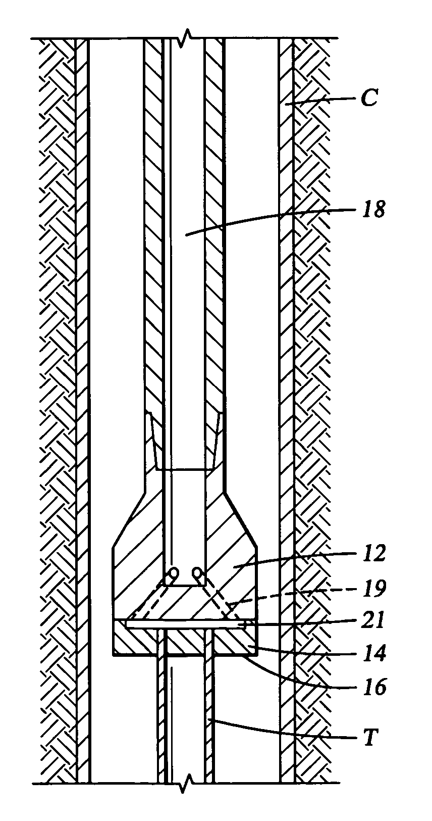
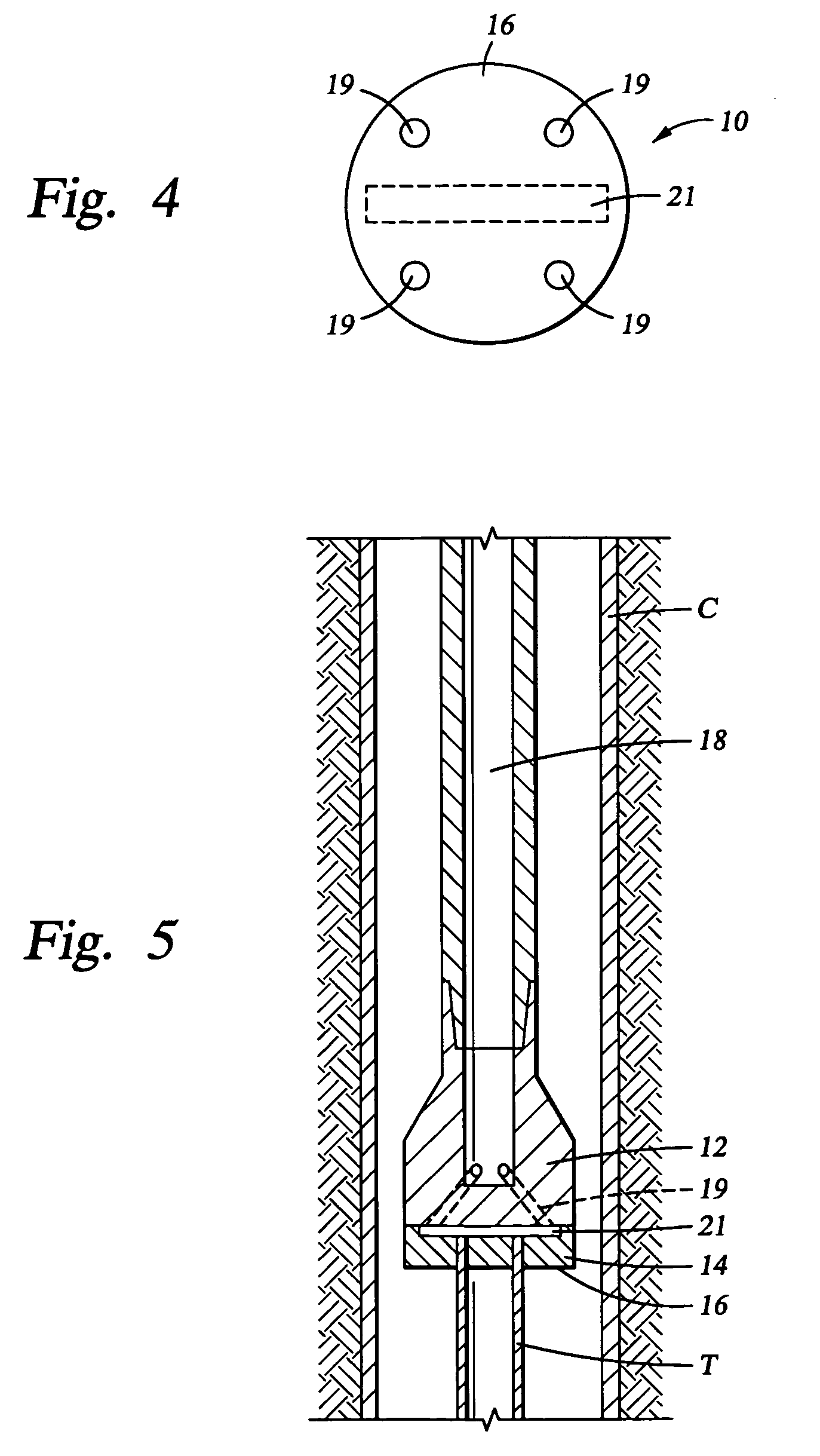
[0023]FIG. 4 shows an end view of a tool 10 according to the present invention. FIG. 5 shows the tool 10 in operation. The tool 10 has a body 12, on which is formed a working profile 14 in the form of a matrix of cutting elements. As the tool 10 is rotated, the leading face 16 of the working profile 14 contacts the tubular element T, and the working profile 14 mills away the tubular element T. As mentioned above, at the same time, the tubular element T will wear a circular groove in the working profile 14. A rectangular, closed-end, fluid passage 21 is formed within the working profile 14, imbedded below the leading surface 16 of the working profile 14. That is, the working profile 14 initially separates the fluid passage 21 from contact with the downhole structure, represented in this case by the tubular element T. Thus, the fluid passage 21 is represented as dashed lines in FIG. 4, and the nozzles 19 are shown leading from the fluid path 18 to the leading face 16. FIG. 4 indicates...

second embodiment

[0025]FIGS. 6 and 7 show the tool 10, which actually includes two additional types of wear indicators. That is, a plurality of closed fluid passages 20, in this case a plurality of branches, are embedded within the cutting profile 14. As with the rectangular fluid passage 21, these fluid branches 20 could be tubes 22 imbedded within the working profile 14, or they could simply be passages formed therein by any known means. These fluid branches 20 function in a similar fashion to the fluid passage 21. Also shown in this embodiment is another type of wear indicator, namely a plurality of pads 24 of wear resistant material.

[0026] When the working profile 14 has worn down as shown in FIG. 7, to the point where the wear resistant pads 24 contact the downhole structure, the wear resistant pads 24 begin carrying a substantial portion of the weight on the tool 10. This essentially prevents any further milling or cutting action, and as a result, the torque required to rotate the tool 10 is s...

third embodiment

[0027]FIG. 8 shows the tool 10, which also includes two types of wear indicator. As with the embodiment shown in FIGS. 6 and 7, the wear resistant pads 24 are shown here, and they function in the same way as described above. Additionally, this embodiment shows a capsule 28 of a discernible medium or material, which functions as a tell-tale agent. As with the rectangular fluid passage 21, the capsule 28 could be a tubes 30 imbedded within the working profile 14, or it could simply be a passage formed therein by any known means. The discernible material might be a magnetic powder, a chemical agent, or any other material which contrasts in some way, such as visibly, with the drilling or milling fluid being pumped through the tool 10. Other discernible properties might also be used, with the key point being that they are discernible to an observer or to some type of instrumentation, once they are released from the tool 10.

[0028] As the downhole structure wears away the working profile 1...


PUM


Abstract

Apparatus and method for monitoring the wear of a downhole tool, and providing indication of the degree of wear to an operator at the well surface. A pressurized fluid path within the cutting element matrix can exhibit a pressure drop when wear of the matrix progresses into the fluid path, or rotating torque can exhibit a drop when wear of the matrix progresses to wear pads within the cutting element matrix. Other wear indicators can also be built into the cutting element matrix. Progression of wear down to the indicator can be directly measured at the well surface, or relayed to the surface via a downhole communication system.

Description

CROSS REFERENCE TO RELATED APPLICATIONS [0001] This application relies upon U.S. Provisional patent application No. 60 / 571,246, filed on May 13, 2004, and entitled “Wear Indication Apparatus and Method.”STATEMENT REGARDING FEDERALLY SPONSORED RESEARCH OR DEVELOPMENT [0002] Not Applicable BACKGROUND OF THE INVENTION [0003] 1. Field of the Invention [0004] This invention is in the field of methods and apparatus used to perform downhole work in a well bore with a tool having a working profile which wears away during use, such as a mill, cutter, or drill bit. [0005] 2. Background Art [0006] In the drilling, completion, and workover of oil and gas wells, it is common to perform work downhole in the well bore with a tool which has some sort of wearable working profile interfacing with a downhole structure. Examples would be milling a downhole metal object with a milling tool, performing a washover operation with a rotary shoe, cutting through a tubular with a cutting tool, or drilling thr...

Claims


Application Information

Patent Timeline
Patent Type & Authority Applications(United States)
IPC IPC(8): B24B51/00B24B49/00E21B10/00E21B12/02
CPCB24B49/08E21B10/00E21B12/02
Inventor LYNDE, GERALD D.DAVIS, JOHN P.
Owner BAKER HUGHES INC
Why Eureka
Try Eureka