Electronic control unit

a control unit and electronic technology, applied in the field of electronic control units, can solve the problems of insufficient noise suppression, inability to meet the requirements of detection signals, and inability to achieve suitable capacitance values of bypass capacitors, so as to achieve the effect of preventing abnormal operation, high noise resistance property, and suppressing electromagnetic nois

Active Publication Date: 2006-05-18
MITSUBISHI ELECTRIC CORP
View PDF2 Cites 11 Cited by
  • Summary
  • Abstract
  • Description
  • Claims
  • Application Information

AI Technical Summary

Benefits of technology

[0012] According to the electronic control unit of the present invention, electromagnetic noise which are induced in a power supply line or a signal line by a strong transmission electric wave from a portable wireless apparatus such as a mobile telephone or a transceiver which is used in a nearby style can be discharged to the ground line through the bypass capacitor, thereby making it possible to suppress the electromagnetic noise.
[0013] In addition, the power supply line through which an electric power is supplied to the analog sensor is powered from the current limiting circuit portion. Thus, even when the power supply line is erroneously grounded, the constant voltage controlling circuit portion is prevented from being damaged, and hence the electronic control unit can be prevented from abnormally operating.
[0014] Also, since other noise generated in an analog signal line are removed through the signal noise absorbing circuit and the integrating circuit portion, it is possible to obtain the electronic control unit which is generally safe and exhibits a high degree of noise resistance property.

Problems solved by technology

As a result, there has been a problem in that the responsibility to a detection signal becomes worse when the capacitance value is excessively large, while the noise cannot be suppressed sufficiently when the capacitance value is too small.
Thus, there has also been encountered a problem in that the suitable capacitance values of the bypass capacitors are not clear.
However, the magnetic signal detecting device disclosed in JP 11-202037 A and the semiconductor integrated circuit device disclosed in JP 2002-043525 A are incapable of handling this problem.

Method used


Image

  • Electronic control unit
  • Electronic control unit
  • Electronic control unit

Examples


embodiment 1

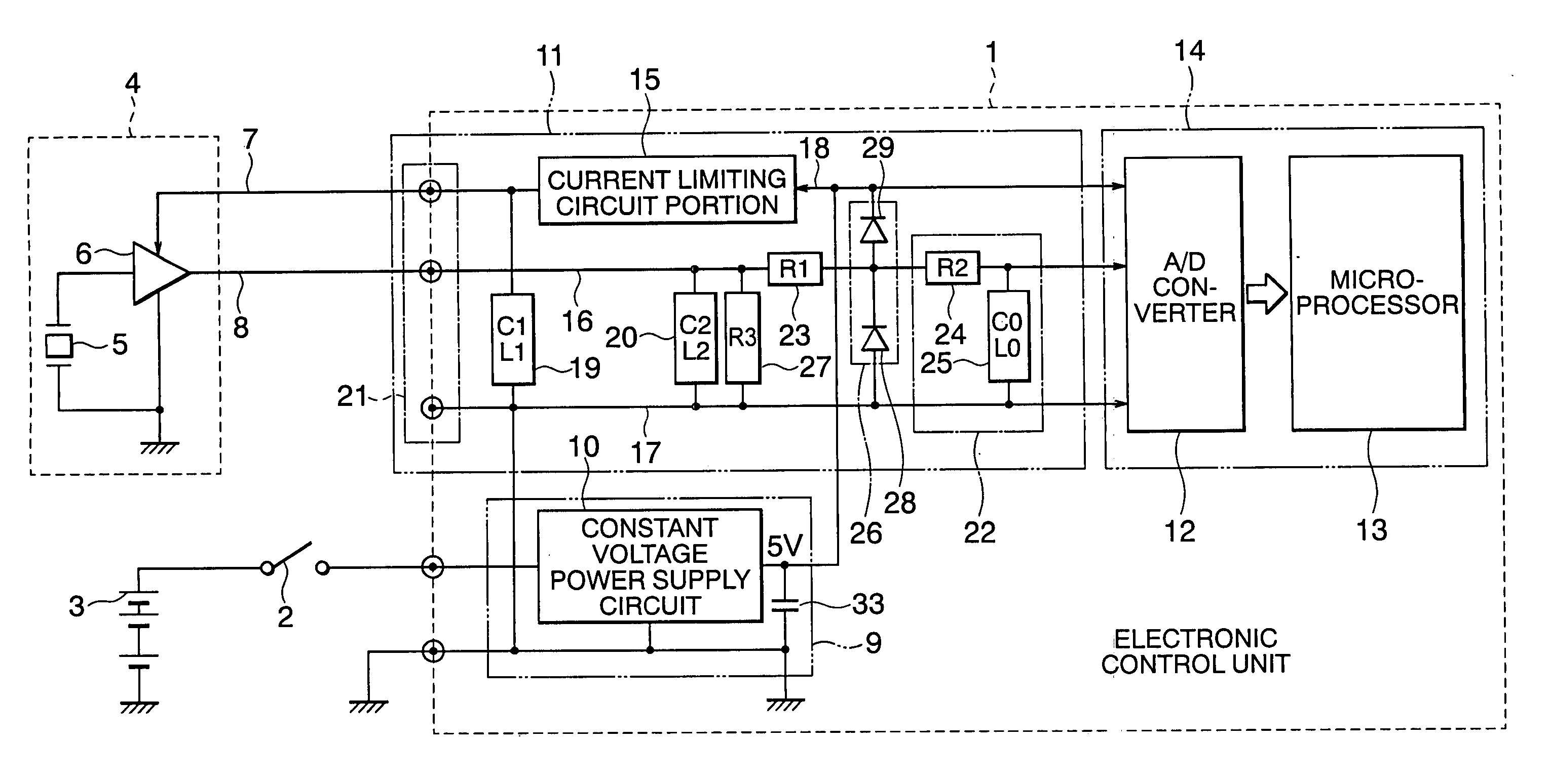
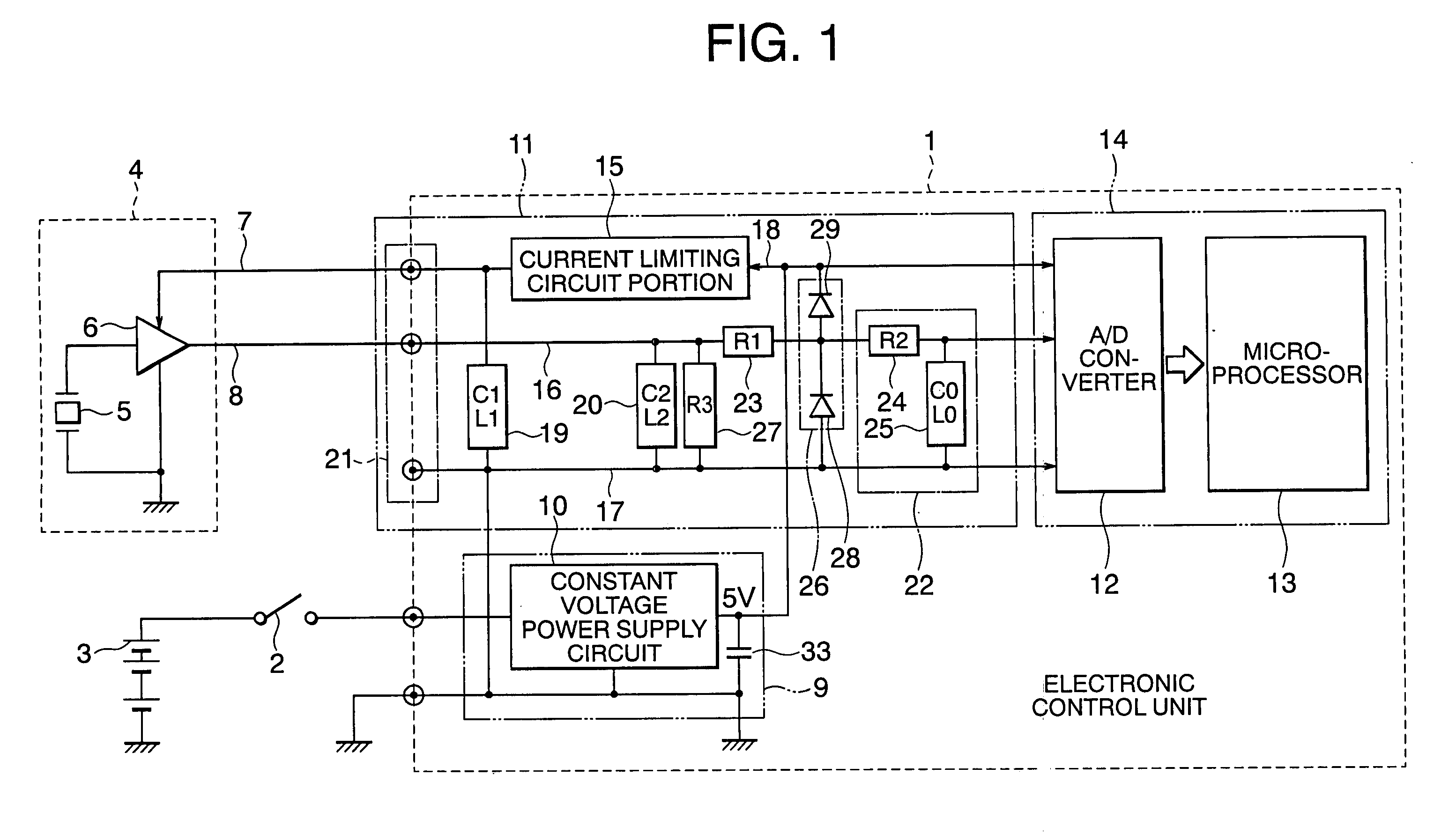
[0020]FIG. 1 is a block diagram, partly in circuit diagram, showing a configuration of an electronic control unit according to Embodiment 1 of the present invention together with a configuration of peripheral units.

[0021] In FIG. 1, a driving power supply 3 which is powered through a power supply switch 2, and an analog sensor 4 for transmitting a detection signal to an electronic control unit 1 are connected from the outside to the electronic control unit 1.

[0022] The analog sensor 4 includes a sensor element 5 as a detection element, and an amplification circuit portion 6 for amplifying a signal outputted from the sensor element 5.

[0023] Here, a power supply line 7 and a signal line 8 through which the analog sensor 4 is connected to the electronic control unit 1 are accommodated in a common wire harness (not shown).

[0024] An electric power for the analog sensor 4 is supplied from the electronic control unit 1 through the power supply line 7, and the detection signal from the ...

embodiment 2

[0081]FIG. 3 is a block diagram, partly in circuit diagram, showing a configuration of an electronic control unit 1A according to Embodiment 2 of the present invention together with a configuration of peripheral units. Here, with respect to the same or corresponding constituent elements to those in Embodiment 1, “A” is added to each of the same reference numerals, and detailed descriptions are omitted.

[0082] In FIG. 3, the electronic control unit 1A as an engine control unit for an automobile is powered by the driving power supply 3 as an on-vehicle battery through the power supply switch 2.

[0083] In addition, the analog sensor 4 includes the sensor element 5 as a pressure sensor for measuring an atmospheric pressure within an inlet pipe, and the amplification circuit portion 6.

[0084] Here, the first bypass capacitor 19 is a chip type ceramic capacitor having an electrostatic capacity of 0.01 to 0.1 μF, and the second bypass capacitor 20 is a chip type ceramic capacitor having an...


PUM


Abstract

This invention provides an electronic control unit is capable of suppressing electromagnetic noise having a frequency band used in a portable wireless apparatus, and capable of exhibiting a noise resistance property against electromagnetic noise. The electronic control unit including a constant voltage power supply circuit portion, an analog signal inputting circuit portion, and a conversion processing circuit portion, an analog sensor and a driving power supply being connected to the outside, and the unit being connected to the analog sensor through a power supply line and a signal line, in which the analog signal inputting circuit portion includes a current limiting circuit portion, an integrating circuit portion, a current limiting resistor, a signal noise absorbing circuit, and a first bypass capacitor, and capacitance (C1) and parasitic inductance (L1) of the first bypass capacitor are set in a range of 7×10⁶<1/[2π✓(LC1)]<35×106.

Description

BACKGROUND OF THE INVENTION [0001] 1. Field of the Invention [0002] The present invention relates to an electronic control unit for suppressing electric wave noise induced in a power supply line and a signal line. [0003] 2. Description of the Related Art [0004] Heretofore, in order to suppress noise in an electronic apparatus, there has often been employed a method of inserting capacitors between a signal line and a ground line, and between positive and negative power supply lines. [0005] As regards a conventional magnetic signal detecting device, in a magnetic signal detecting device utilized in a mobile communication apparatus such as a mobile telephone or a cordless telephone, an output signal from a magnetic resistance element constituted by a resistance bridge is grounded by employing a structure in which a non-inverted input terminal of a diffractive type operational amplification circuit constituted by a first operational amplifier and a second operational amplifier is ground...

Claims


Application Information

Patent Timeline
Patent Type & Authority Applications(United States)
IPC IPC(8): H02H3/08H02H9/02
CPCH02H9/005H02H9/046
Inventor YUHARA, MASAHARUSHIRAKI, YASUHIROOKISHIO, KAZUHITONAKAMURA, HIROSHIUMEMARU, HISATOTAKAHATA, YOSHIMITSUGOTOH, YASUAKI
Owner MITSUBISHI ELECTRIC CORP
Why Eureka
Try Eureka