Air filter

a filter and air technology, applied in the field of air filters, can solve the problems of large production complexity, large partial pressure loss, and hydrocarbons present in the intake manifold of an internal combustion engine, and achieve the effects of facilitating and simplifying the flow, minimizing pressure loss, and enhancing both adsorption and desorption

Inactive Publication Date: 2006-05-25
MANN HUMMEL GMBH
View PDF17 Cites 31 Cited by
  • Summary
  • Abstract
  • Description
  • Claims
  • Application Information

AI Technical Summary

Benefits of technology

[0009] Another object of the invention is to provide an air filter which can inhibit the emission of hydrocarbons to the ambient environment.
[0023] It is also possible, however, to dispose the element having the adsorbent particles on the filtered air outlet, concentrically to the filtered air outlet. In this case, the element having the adsorbent particles preferably has the shape of a truncated cone, such that the inside diameter of the open end face, which protrudes into the interior of the housing, approximately matches the inside diameter of the filtered air outlet. This again minimizes the pressure loss caused by the element having the adsorbent particles.

Problems solved by technology

In connection with the above-described SULEV / ULEV problem, the disadvantage, however, is that hydrocarbons present in the intake manifold of an internal combustion engine, for example, may escape into the environment when the engine is stopped.
Drawbacks in all of these solutions include their substantial production complexity, the considerable partial pressure loss and the required special adaptation of the housings and air ducts to the adsorber elements.
A further problem is the need for desorbing the adsorber elements, which is typically done while the internal combustion engine is running.
In an adsorber element in which the air sweeps over the element, the desorption rate may be inadequate.

Method used


Image

  • Air filter
  • Air filter

Examples


Embodiment Construction

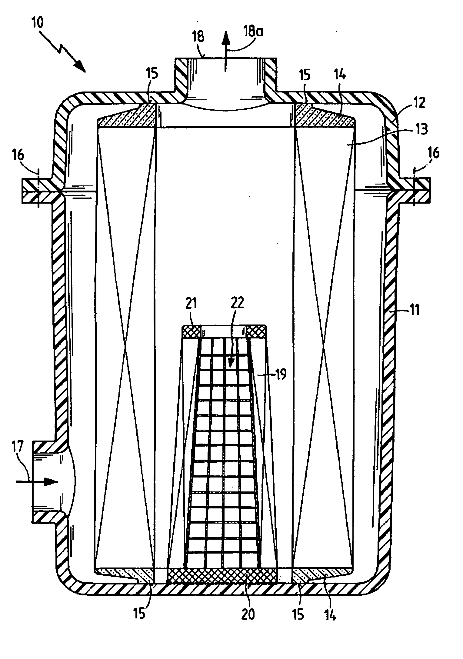
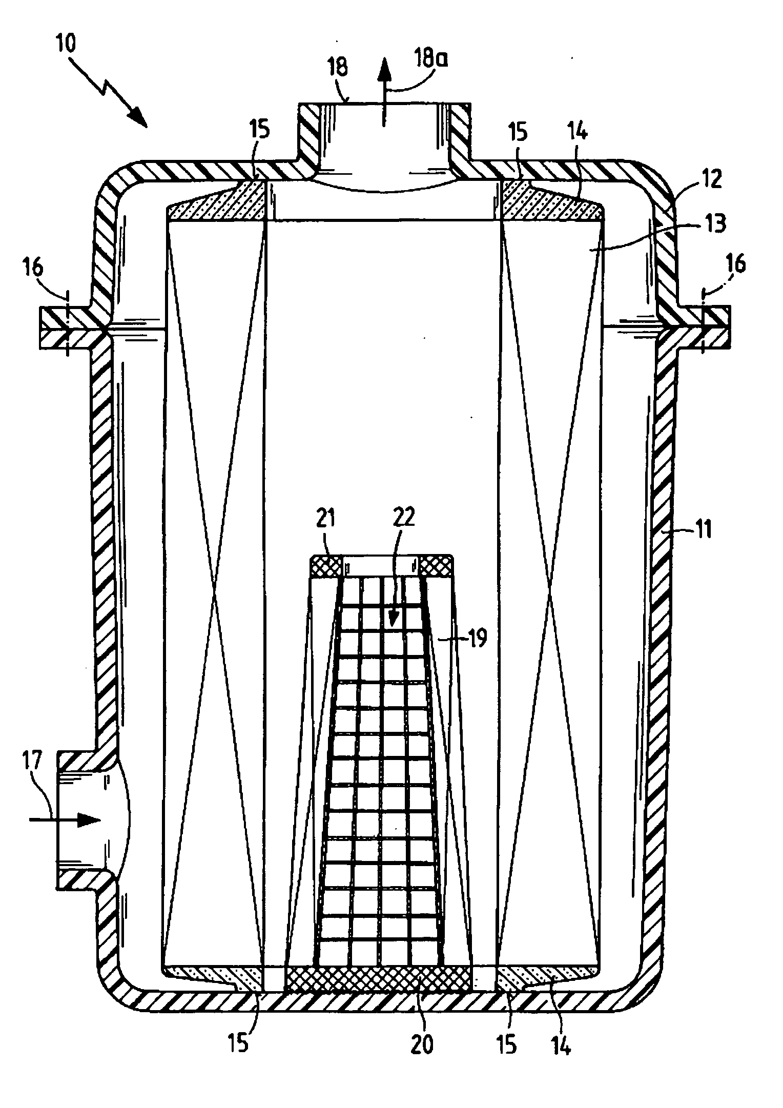
[0028] The FIGURE shows an air filter 10 having a lower housing section 11 and an upper housing section 12. A round filter element 13, which has an open end disk 14 on each of its end faces, is sealingly disposed within the housing sections 11, 12. The round filter element 13 preferably has a zigzag-type pleated filter medium made, for example, of paper or a nonwoven material.

[0029] The end disks 14 are made of a soft, flexible seal material, such as polyurethane foam. Because they axially contact the respective housing sections 11, 12 in the contact region 15, the end disks 14 establish an axial seal between an unfiltered side and a filtered side. The two housing sections 11, 12 are interconnected by a positive-locking and airtight connection 16. The lower housing section 11 has an air inlet 17 for the intake air to be filtered, and the upper housing section 12 has an air outlet 18a for the filtered intake air.

[0030] In the interior of the round filter element 13 an adsorber elem...


PUM

PropertyMeasurementUnit
shapeaaaaaaaaaa
structureaaaaaaaaaa
partial pressure lossaaaaaaaaaa

Abstract

An air filter, particularly an air filter for an internal combustion engine, having a housing with an unfiltered air inlet and a filtered air outlet. A round filter element is sealingly disposed between the unfiltered air inlet and the filtered air outlet. In addition, an adsorber element provided with adsorbent particles is disposed on an interior wall of the housing such that the adsorber element is arranged within the round filter element.

Description

BACKGROUND OF THE INVENTION [0001] The present invention relates to an air filter comprising a housing with an unfiltered air inlet and a filtered air outlet, and a round filter element sealingly disposed in the housing between the unfiltered air inlet and the filtered air outlet. [0002] An essential development goal in modern internal combustion engines is to reduce emission of harmful substances. Until now, the development activities have focused primarily on optimizing the exhaust emission control system. Modern exhaust emission control systems meanwhile achieve conversion rates for harmful substances greater than 97%. [0003] Increasing air pollution has led most countries to limit emissions and to continue to tighten these limits. To assure reproducibility and comparability, various test methods, ratings and limits have been developed. In the United States, for example, the limits include the categories ULEV (Ultra Low Emission Vehicle), SULEV (Super Ultra Low Emission Vehicle) ...

Claims


Application Information

Patent Timeline
Patent Type & Authority Applications(United States)
IPC IPC(8): B01D53/02
CPCB01D46/0024B01D46/0036B01D46/2411B01D46/521B01D2253/102B01D2275/201B01D2279/60F02M25/08F02M35/024B01D46/64
Inventor MAIER, STEFANPFEIFFER, FRANK
Owner MANN HUMMEL GMBH
Why Eureka
Try Eureka