Adhesive optical film, method for manufacturing adhesive optical film and image display

a technology of adhesive optical film and adhesive adhesive, which is applied in the direction of film/foil adhesive, polarising elements, synthetic resin layered products, etc., can solve the problems of defective display, defective display, dropped adhesive, etc., and achieve the effect of obtaining more easily and more simply

Active Publication Date: 2006-05-25
NITTO DENKO CORP
View PDF1 Cites 116 Cited by
  • Summary
  • Abstract
  • Description
  • Claims
  • Application Information

AI Technical Summary

Benefits of technology

[0006] The present invention aims to provide more simply and more easily an adhesive-type optical film that has an adhesive layer laminated on one side or both sides of an optical film and hardly suffers adhesive chips and adhesive contamination during transport and handling, or on the manufacturing and processing-operation lines. Further, the present invention aims to provide a method for producing the adhesive-type optical film and image display device using the adhesive-type optical film.
[0010] In accordance with the present invention, the adhesive layer of an adhesive-type optical film having an adhesive layer laminated on one or both sides of an optical film locates on the inside of the optical film's edge lines, and thereby the adhesive-type optical film resistant to bringing about not only contamination with the adhesive pushed out from the edges (adhesive contamination) but also adhesive chips during transport and handling or on the manufacturing and processing-operation lines can be obtained more easily and more simply than ever.

Problems solved by technology

When the aforementioned adhesive-type optical films are, e.g., transported, handled, or conveyed on the manufacturing and processing-operation lines, a defective situation, specifically a phenomenon that the adhesives in edges of the adhesive-type optical films are dropped out in a chipped state due to contact between the optical films' ends and substances of some kinds (hereinafter referred to as “adhesive chips”), is brought about at externally unprotected side faces of the adhesive layers.
In addition, there occurs a case where dropped-out adhesive contaminates the surfaces of optical films (hereinafter referred to as “adhesive contamination”).
If once adhesive chips occurs, secure bonding becomes impossible, and what is worse, the chipped parts form an air layer and come to have different refractive index and vibration direction from other parts, thereby becoming a cause of defective display.
Likewise, the adhesive contamination also causes defective display.
However, these methods involve contamination with an extraneous substance, such as powder or a sprayed coat, or require complex processes.

Method used


Image

  • Adhesive optical film, method for manufacturing adhesive optical film and image display
  • Adhesive optical film, method for manufacturing adhesive optical film and image display
  • Adhesive optical film, method for manufacturing adhesive optical film and image display

Examples


example 1

(Preparation of Acrylic Polymer)

[0101] In a separable flask equipped with a thermometer, a stirrer, a reflux condenser and a nitrogen-gas introduction tube, 97 parts of butyl acrylate, 3 parts of acrylic acid, 0.2 parts of azobisisobutyronitrile and ethyl acetate in an amount required for adjusting the solid contents to 30% were set, and then nitrogen replacement was carried out for about 1 hour while admitting nitrogen gas into the flask and stirring the ingredients put in the flask. Thereafter, reaction was run for 7 hours while heating the flask at 60° C. to yield an acrylic polymer having a weight average molecular weight (Mw) of 1,000,000.

(Preparation of Adhesive Composition)

[0102] An adhesive composition (in solution form) was prepared by admixing the acrylic polymer prepared in the foregoing manner (100 parts on a solids basis) with 10 parts of butyl acrylate (BA) oligomer (Mw=3,000), 0.8 parts of trimethylolpropane tolylenediisocyanate as a cross-linking agent of isocya...

example 2

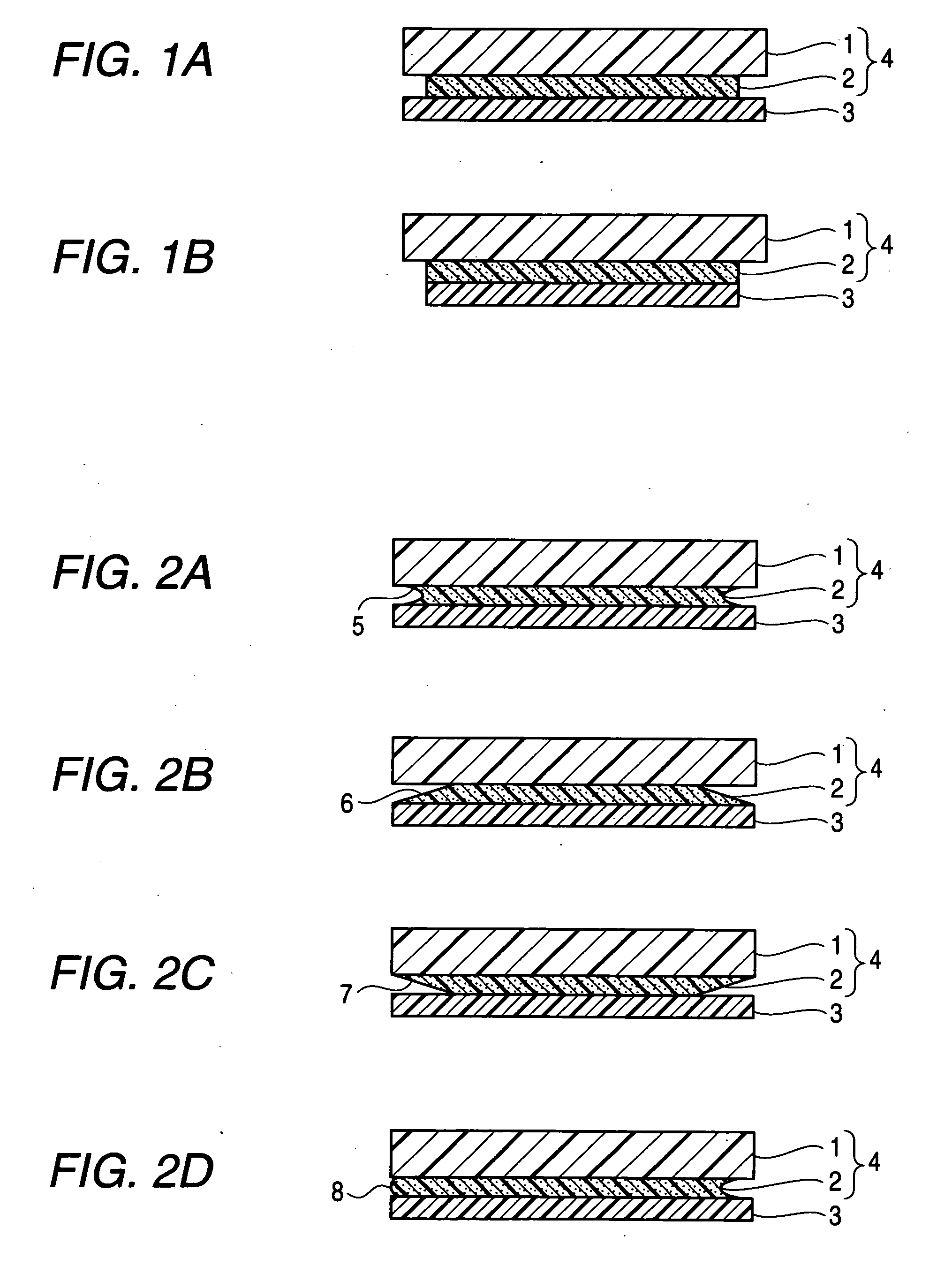
[0104] An adhesive-type polarizing plate was made by laminating, on the polarizing plate stamped into the size of 11 inches by means of a Thomson blade as used in Example 1 (for making another adhesive-type optical film), an adhesive-applied release film made by applying a coating of the same adhesive solution as prepared in Example 1 to a 38 μm-thick release film of polyethylene terephthalate-based so as to cover the entire area of 11-inch size and have a dry thickness of 25 μm and then drying the coating at 100° C. for 4 minutes to form an adhesive layer (loss elasticity modulus: 8.0×10⁴ Pa (25° C.)). Fifty sheets of the thus made adhesive-type polarizing plate were stacked on top of each other, and pinched at the top and the bottom with a jig shaped like a vise while controlling pressure so that the adhesive extruded from the edges. In just the pressurized state they were, the adhesive layers were cut together with the optical films at the position 1.0 mm away in an inward direct...

example 3

[0105] An adhesive-type polarizing plate was made by laminating, on the polarizing plate stamped into the size of 11 inches by means of a Thomson blade as used in Example 1 (for making another adhesive-type optical film), an adhesive-applied release film made by applying a coating of the same adhesive solution as prepared in Example 1 to a 38 μm-thick release film of polyethylene terephthalate-based so as to cover the entire area of 11-inch size and have a dry thickness of 40 μm and then drying the coating at 100° C. for 4 minutes to form an adhesive layer (loss elasticity modulus: 1.1×10³ Pa (25° C.)). Fifty sheets of the thus made adhesive-type polarizing plate were stacked on top of each other, and pinched at the top and the bottom with a jig shaped like a vise while controlling pressure so that the adhesive extruded from the edges. In just the pressurized state they were, the adhesive extruded out of the optical film edges was cut away with a rotary blade. Thereafter, the stacke...


PUM

PropertyMeasurementUnit
distanceaaaaaaaaaa
storage modulusaaaaaaaaaa
temperatureaaaaaaaaaa

Abstract

An adhesive layer included in an adhesive-type optical film forms a portion located on the inside of a edge line of an optical film.

Description

FIELD OF THE INVENTION [0001] The present invention relates to an adhesive-type optical film that has an adhesive layer laminated on one side or both sides of an optical film. Further, the present invention relates to an adhesive-type optical film that includes the aforementioned adhesive-type optical film and at least one layer selected from a release film, an optical layer, an optical film and an adhesive layer, and an image display device such as a liquid crystal display (LCD), an electroluminescence display (ELD), a plasma display panel (PDP) and a field emission display (FED), wherein the aforementioned adhesive-type optical film is used. BACKGROUND ART [0002] Placement of polarizing plates on both sides of a glass substrate, which forms the outermost face of a liquid-crystal panel, is indispensable for a liquid crystal display because of the picture formation system adopted therein, and a polarizing plate is generally stuck on the outermost face of a liquid-crystal panel. In a...

Claims


Application Information

Patent Timeline
Patent Type & Authority Applications(United States)
IPC IPC(8): B32B17/00B32B3/02B32B7/02C09J7/02C09J133/00G02B5/30G02F1/1335H01L51/50H05B33/02H05B33/14
CPCB32B3/02Y10T428/24198B32B7/06B32B7/12B32B27/08B32B27/36B32B2250/42B32B2307/40B32B2307/748B32B2405/00B32B2551/00G02B5/3025B05D5/10Y10T428/14Y10T428/1476Y10T428/24777Y10T428/28Y10T428/219B32B3/263G02B5/30
Inventor SATAKE, MASAYUKIKAWAGUCHI, MASAAKIITANO, NOBORUOGASAWARA, AKIKOHAYASHI, OSAMU
Owner NITTO DENKO CORP
Why Eureka
Try Eureka