
Method and device for processing biowaste

a biowaste and processing method technology, applied in the field of biowaste processing methods and devices, can solve the problem of reducing the efficiency of the separation devi

Inactive Publication Date: 2006-05-25
SBM MASCHEN
View PDF1 Cites 0 Cited by
  • Summary
  • Abstract
  • Description
  • Claims
  • Application Information

AI Technical Summary

Benefits of technology

[0039] The advantage of the invention is in particular the fact that the sequences mentioned above are designed module-like, and can be used and recalled on demand by the control.
[0040] It is, of course, also possible to install a suitable cleaning sequence for the comminution mill.
[0041] For the case that an accident is determined by the control, for example by the waste recognition sensors or the level sensors, it is possible and even convenient that the control starts a trouble sequence where the control stops the comminution mill, and the pump conveys still present crumbled biowaste mash to the separation device, the separation device still separates it accordingly, and, after that, the control carries out, if necessary a cleaning sequence. For the case that the level sensors point to an accident, of course, a suitable reserve has to be provided in order to allow a complete emptying of the device. Stopping the comminution mill interrupts the supply of waste mash, for the case that impurities or troubling waste are found in the support region, an early stopping of the comminution mill protects it.
[0042] Advantageously the pump is designed as impeller pump. Impeller pumps have the advantage that they are designed indifferently on the position, and that they are dry, self-priming.
[0043] Therefore they may even in empty condition apply the complete device.
[0044] The invention refers also to a method for processing biowaste, the biowaste being crumbled, respectively ground, in a comminution mill, and a separation device arranged after that separating the crumbled biowaste into solid material and liquids, pressure and / or flow of the ground biowaste being monitored and, if necessary, the pressure, respectively the flow, of the ground biowaste being adjusted, in particular increased or reduced, by a pump. In such a method according to the invention the secure, trouble-free and also automatic operation is secured, and a constant load of the separation device is reached, so that as a last consequence it has not to be over-dimensioned in order to intercept corresponding processing peaks.

Problems solved by technology

The efficiency of the separation device decreases, of course, when the inlet flow of waste mash is accordingly unsteady.

Method used


Image

  • Method and device for processing biowaste
  • Method and device for processing biowaste

Examples


Embodiment Construction

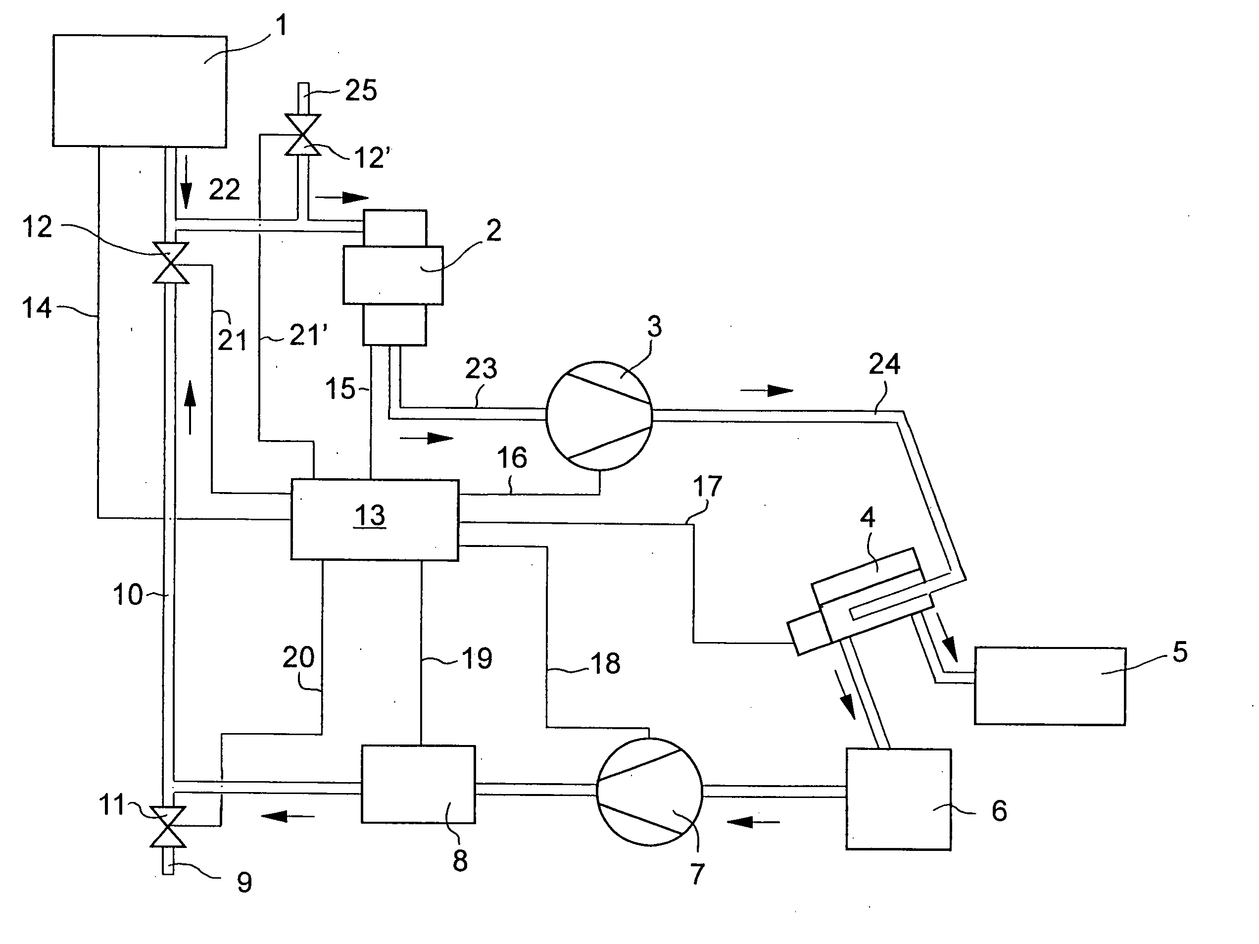
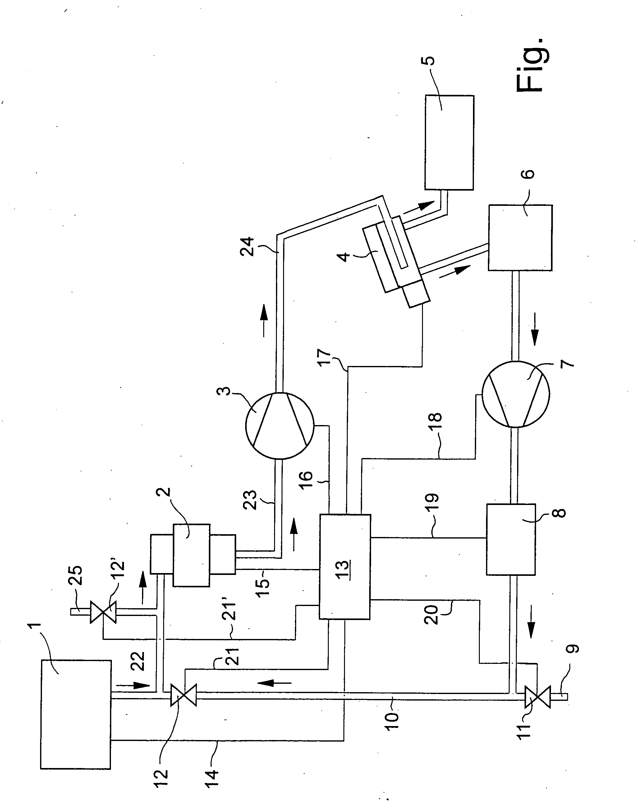
[0047] The device according to the invention can be described as follows. The biowaste is deposited in the support region 1. Through the connection drawn as pipe 22 it gets in the comminution mill 2. The comminution mill 2 generates a waste mash the ability of which to be pumped or flow depends essentially on the size of the water content of the introduced good.

[0048] The direction of conveying of the biowaste, the liquid and so on is indicated by arrows.

[0049] The waste mash produced in comminution mill 2 is conveyed through the suction pipe 23, the pump 3 and a pump pipe 24 in the separation device 4. The separation device 4 effects a separation of the solid material from the liquid contained in the waste mash. Collecting container 5 is available for the solid material. Also for liquids a collecting container is provided with the reference number 6.

[0050] The separation device 4 is designed, for example, as press or the like.

[0051] The liquid collected in the collecting contai...


PUM


Abstract

The invention refers to a method and a device for processing biowaste. A comminution mill is provided after which a separation device for solid materials and liquids is arranged. A control monitors pressure, respectively flow, of the biowaste ground by the comminution mill, and adjusts, depending on these monitored values, a pump which is arranged before the separation device.

Description

[0001] The invention refers to a method and a device for processing biowaste, comprising a comminution mill and a separation device which is arranged after it for solid materials and liquids. BACKGROUND OF THE INVENTION [0002] Devices mentioned above are known, for example, from the German patent application 101 08 495.1 by the applicant. They are used for processing organic waste of the type which occurs in the food processing industry and in joint catering institutions like, for example, canteen kitchens, canteens or in big events. In particular the processing of biowaste is supposed to make its disposal easier. [0003] In order to dispose of this biowaste it has been known, to use it, for example, in agriculture as food. However, because of epidemic-hygienic regulations this biowaste has to be pre-processed in a suitably expensive manner. [0004] Organic waste has a very high content of water of up to 80%. These are often leftovers of fruit and vegetable, fish and meat waste, howev...

Claims


Application Information

Patent Timeline
Patent Type & Authority Applications(United States)
IPC IPC(8): B02C23/00
CPCB03B9/06B09B3/00C05F9/00C05F9/02Y02W30/52Y02A40/20
Inventor STEINBECK, JOACHIM
Owner SBM MASCHEN
Learn More