
Defect inspection method for perpendicular magnetic recording medium, magnetic disk device, and method of registering defects in magnetic disk device having a perpendicular magnetic recording medium therein

a technology of perpendicular magnetic recording medium and inspection method, which is applied in special recording techniques, magnetic recording, magnetic measurement, etc., can solve the problems of reversal of magnetization, affecting affecting the stability of magnetization, so as to improve the registration accuracy of defects, improve the coercivity of the medium, and efficiently detect the defect in the medium

Inactive Publication Date: 2006-05-25
HITACHI GLOBAL STORAGE TECH NETHERLANDS BV
View PDF5 Cites 13 Cited by
  • Summary
  • Abstract
  • Description
  • Claims
  • Application Information

AI Technical Summary

Benefits of technology

[0010] The present invention has been made for solving the above problems, and a feature of the invention is to provide a defect inspection method that allows efficient detection of defects in a perpendicular magnetic recording medium, especially of defects due to magnetization reversal. Another feature of the invention is to provide a magnetic disk device in which are suppressed the decreases in device performance and signal reliability that are likely to result from signal quality deterioration due to defects. Yet another feature of the invention is to provide an accuracy-improved method for registering defects in a magnetic disk device.
[0014] According to the present invention, a signal present on a perpendicular magnetic recording medium is rendered unstable by direct-current erasing, and then the coercivity of the medium is deteriorated by heating it to accelerate the reversal of magnetization in defective sections. It is possible, by conducting defect inspections after that, to efficiently detect defects in the medium, more particularly, defects due to magnetization reversal. Also, registering detected defects in a similar manner in a magnetic disk device improves registration accuracy of the defects. In addition, it is possible to obtain a magnetic disk device whose decreases in device performance and signal reliability due to defects are suppressed.

Problems solved by technology

In particular, if manufacturing-related, very small, nonuniform sections occur, this easily causes the reversal of magnetization due to the demagnetizing field.
Accordingly, even if the desired direction of magnetization can be given in the perpendicular magnetic recording medium by the write operation, sections in which the magnetization becomes unstable and easily reverses are likely to be formed longitudinally inside the medium.
There has been the problem that these sections prone to suffer the reversal of magnetization under the influence of a demagnetizing field are difficult to accurately detect during the signal read / write inspections and air-bearing surface asperity measurements performed in the conventional disk independent inspection process taking place before the reversal actually occurs.
That is, since defective sections prone to suffer the reversal of magnetization become elicited primarily after medium mounting in the storage device, the number of defects registered is likely to exceed an upper-limit value and increase the frequency of storage device repair associated with medium replacement during the inspections in the processes following medium mounting in the storage device.

Method used


Image

  • Defect inspection method for perpendicular magnetic recording medium, magnetic disk device, and method of registering defects in magnetic disk device having a perpendicular magnetic recording medium therein
  • Defect inspection method for perpendicular magnetic recording medium, magnetic disk device, and method of registering defects in magnetic disk device having a perpendicular magnetic recording medium therein
  • Defect inspection method for perpendicular magnetic recording medium, magnetic disk device, and method of registering defects in magnetic disk device having a perpendicular magnetic recording medium therein

Examples


Embodiment Construction

[0025] Modes of embodiment of the present invention (hereinafter, referred to simply as embodiments) are described hereunder, pursuant to the accompanying drawings.

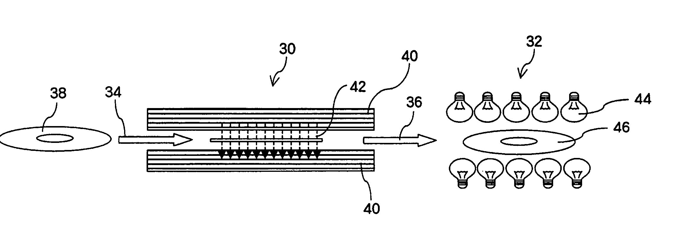
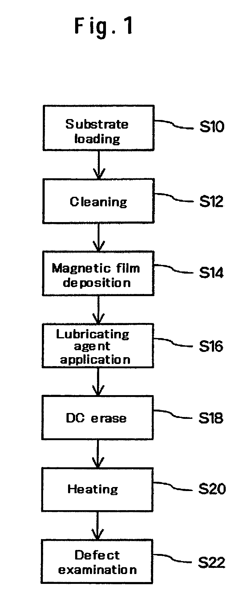
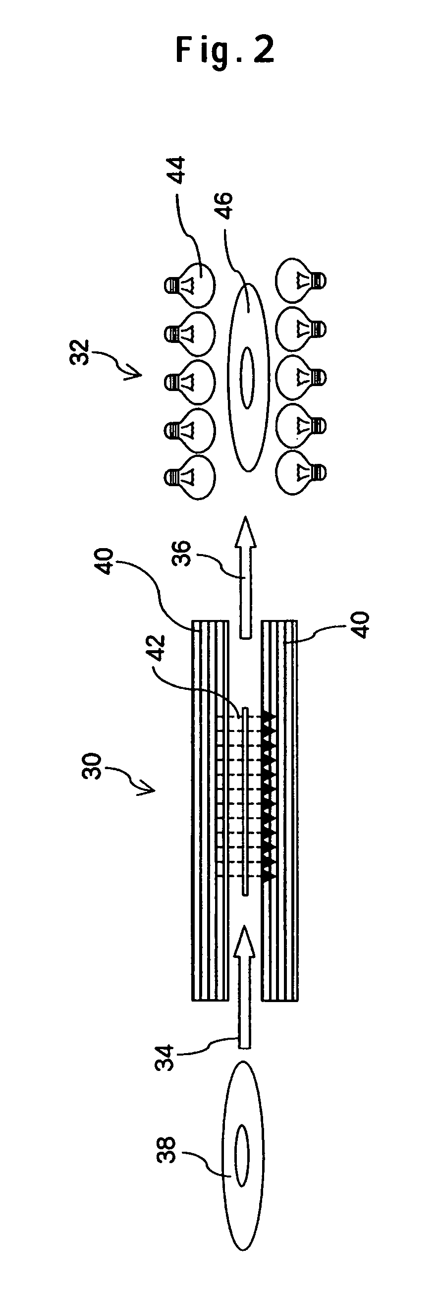
[0026]FIG. 1 is a flow diagram that explains a defect inspection method for a perpendicular magnetic recording medium according to an embodiment of the present invention. The diagram also outlines manufacturing process steps for the medium. This defect inspection method is intended to inspect defects in the medium alone before it is built into a recording device. The medium is manufactured using, for example, an aluminum substrate provided with Ni—P plating. After being loaded for manufacturing processes in step S10, the substrate is cleaned in step S12 as a pre-process for depositing a magnetic film on the medium. Cleaning process step S12 may be preceded by a process step for forming depressions and projections on the substrate surface. After cleaning process step S12, a magnetic film with perpendicular magnetic anisot...


PUM


Abstract

Because of its characteristics, a perpendicular magnetic recording medium has the inconvenience that since sections with low signal stability due to magnetic defects are not easily detectible in advance, these sections are detected after mounting of the medium in a magnetic disk device or after product shipping. According to one embodiment, in the manufacturing processes for the perpendicular magnetic recording medium, a DC-erase process step for direct-current demagnetizing the medium is performed after a magnetic film deposition process step and a lubricating-agent application process step. This maximizes the effects of a demagnetizing field and intentionally increases directional instability of magnetization. After the above processes, the medium is further provided with a heating process to accelerate the reversal of magnetization in latent defective sections. A defect examination step for detecting the magnetization reversal sections on the basis of changes in the baseline of the signal read out from the medium under the above state is performed, whereby defects can be detected efficiently.

Description

CROSS-REFERENCES TO RELATED APPLICATIONS [0001] This application claims priority from Japanese Patent Application No. JP2004-338478, filed Nov. 24, 2004, the entire disclosure of which is incorporated herein by reference. BACKGROUND OF THE INVENTION [0002] The present invention relates to a defect inspection method for a perpendicular magnetic recording medium, to a magnetic disk device, and to a method of registering defects in a magnetic disk device having a perpendicular magnetic recording medium therein. [0003] Storage devices based on magnetic recording technology are most commonly used in products such as computers, workstations, and digital electrical household appliances. In recent years, the extension of these storage devices in storage capacity has been increasingly accelerated with increases in the volumes of information recorded. The storage devices under these situations include magnetic disk devices available at relatively low prices and capable of achieving both a hig...

Claims


Application Information

Patent Timeline
Patent Type & Authority Applications(United States)
IPC IPC(8): G01R33/12
CPCG01R33/1207G11B5/4555G11B19/04G11B27/36G11B2005/001G11B2005/0029
Inventor MAKINO, KIYOSHIMATSUDA, YOSHIBUMI
Owner HITACHI GLOBAL STORAGE TECH NETHERLANDS BV
Learn More