
Timing bias compensation for a data receiver with decision-feedback equalizer

a data receiver and decision-feedback equalizer technology, applied in the field of data receivers, can solve the problems of degrading data recovery, adding significant levels of inter-symbol interference (isi) to a high-speed data stream, and dfe systems including additional complexity to determine the feedback tap weight adaptively, so as to improve jitter tolerance and reduce bit-error rate

Inactive Publication Date: 2006-05-25
GLOBALFOUNDRIES INC
View PDF11 Cites 30 Cited by
  • Summary
  • Abstract
  • Description
  • Claims
  • Application Information

AI Technical Summary

Benefits of technology

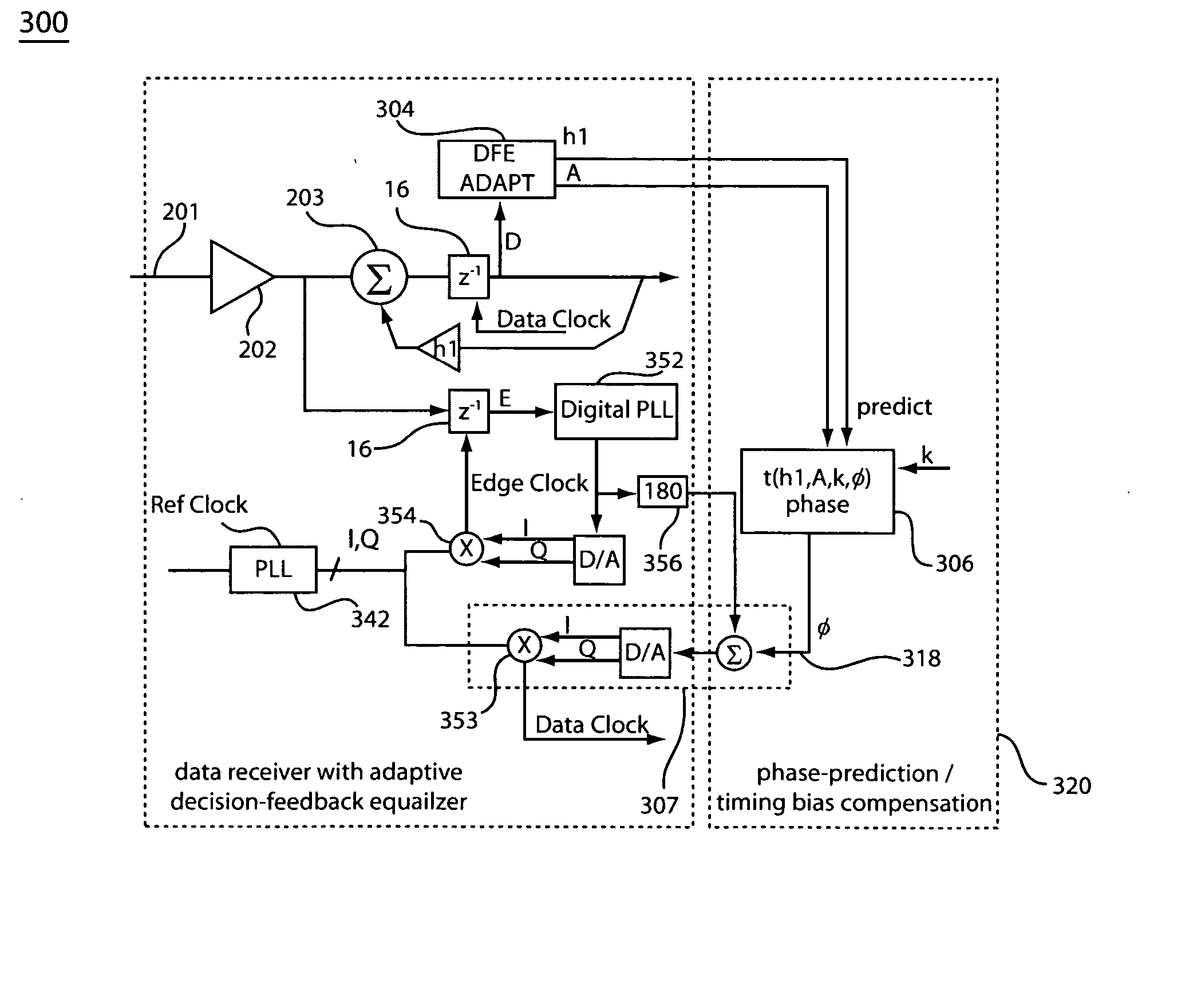
[0018] The exemplary embodiments of present disclosure will address a way to determine and apply an adjustable data clock timing offset to compensate for the DFE bias effect to improve jitter tolerance and lower bit-error rate of a data transmission system which employs decision-feedback equalization in the data detection path.

Problems solved by technology

As data rates for serial interfaces begin to exceed 3 to 4 Gb / s, bandwidth limitation due to conductor skin-effect loss and board material dielectric loss, and impedance mismatches due to board through-vias, non-ideal packaging, and integrated circuit parasitics can add significant levels of inter-symbol interference (ISI) to a high speed data stream.
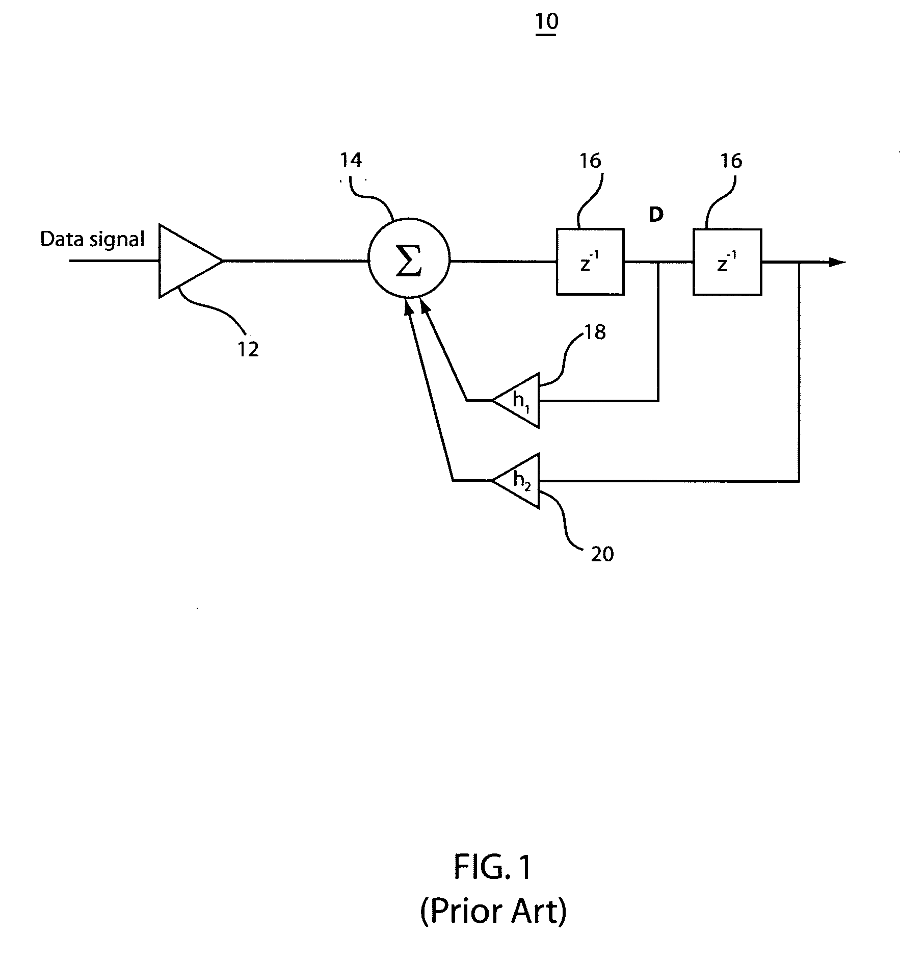
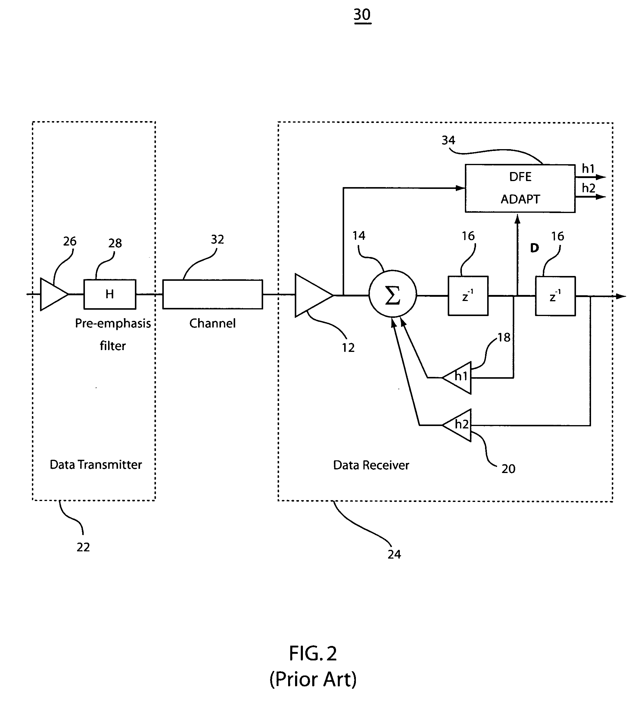
Most practical DFE systems include additional complexity to determine the feedback tap weights adaptively.
The alternating 1010 . . . sequence produces a high frequency signal on the line, which is normally highly attenuated due to channel characteristics, which roll off at high frequency, resulting in degraded data recovery.
Problems can arise with conventional CDR systems (such as those diagrammed in FIGS. 3A and 3B) when a DFE is used with regard to optimum sampling time of the received data waveform.
This timing bias degrades the receiver jitter tolerance, or ability of the receiver to correctly decode data given varying time drift on the transmitter / receiver clocks, since a transmit or receive clock can jitter less on one side of the sampling point than on the other side of the sampling point before data decode becomes unreliable.

Method used


Image

  • Timing bias compensation for a data receiver with decision-feedback equalizer
  • Timing bias compensation for a data receiver with decision-feedback equalizer
  • Timing bias compensation for a data receiver with decision-feedback equalizer

Examples


Embodiment Construction

[0030] A method and apparatus for providing a timing bias compensation for a data receiver system, which employs a decision-feedback equalizer (DFE) are described. Exemplary embodiments make use of a linear approximation formula based on a normalized first decision-feedback tap weight. The formula provides a timing bias estimate, which is employed to adjust the phase relationship between a data clock and an edge clock to advance or delay the data sampling point of a receiver system. Application of the timing bias compensation provides a data sampling time closer to a center of a DFE corrected eye diagram, improving jitter tolerance of a data receiver system.

[0031] Exemplary embodiments provide a method for realizing a time-corrected sampling point for a received waveform, which has been conditioned with decision-feedback equalization (DFE) in a data receiver system. A general embodiment provides a method for determination of a time-correction value for a data sampling point of a re...


PUM


Abstract

A phase adjustment apparatus and method adjusts phase or timing bias of a sample clock in a data receiver system by determining a time adjustment value as a function of equalizer feedback. The time adjustment value is then applied to a device capable of adjusting a timing bias of a sample clock.

Description

BACKGROUND [0001] 1. Technical Field [0002] The present invention relates to data receivers, and more particularly to an apparatus, system and method, which provides an improved timing bias compensation circuit for receivers with decision feedback equalization. [0003] 2. Description of the Related Art [0004] Modern high-speed serial input / output (I / O) interfaces increasingly rely on the addition of receiver equalization systems to compensate channel distortion effects arising from such impairments as bandwidth limitation and line / termination impedance mismatches. As data rates for serial interfaces begin to exceed 3 to 4 Gb / s, bandwidth limitation due to conductor skin-effect loss and board material dielectric loss, and impedance mismatches due to board through-vias, non-ideal packaging, and integrated circuit parasitics can add significant levels of inter-symbol interference (ISI) to a high speed data stream. [0005] One well-known approach to combat the ISI distortion problem makes...

Claims


Application Information

Patent Timeline
IPC IPC(8): H04L7/00H04B1/10
CPCH04L7/0058H04L7/0334H04L25/03057H04L2025/0349
Inventor BEUKEMA, TROYPARKER, BENJAMIN DANFORDSELANDER, KARL DAVIDSORNA, MICHAEL A.
Owner GLOBALFOUNDRIES INC
Learn More