Method for operation of laser

a laser and laser technology, applied in the field of laser operation, can solve the problems of ineffective invention, permanent loss of vision, disruption and disintegration of rpe cells,

Active Publication Date: 2006-05-25
MEDIZINISCHES LASERZENTRUM LUEBECK GMBH
View PDF9 Cites 74 Cited by
  • Summary
  • Abstract
  • Description
  • Claims
  • Application Information

AI Technical Summary

Benefits of technology

[0031] An attenuating unit for rapidly reducing the laser power applied to the irradiated tissue, and located in the laser beam path, permits comparable conditions in connection with the detected transients.

Problems solved by technology

However, the production of temperatures lethal to the diseased cells through laser light absorption gives rise to potentially further damage to the surrounding tissue, which can lead to the necrosis of the non-regenerating photoreceptors and therefore to permanent loss of vision.
The resulting micro-bubbles for μs increase the cell volume and in all probability ultimately lead to the disruption and disintegration of the RPE cell.
However, a previously made choice regarding the laser energy for the same reason can be too low in order to influence the RPE, which renders the invention ineffective.
However, this invasive procedure cannot be carried out in standard ophthalmic practices and consequently, at present, the therapy is restricted to well equipped clinics or university eye hospitals.
Particularly with inadequate treatment results up to the decomposition of the dyes, there can be no direct continuation of the treatment and the fundamentally toxic action thereof often requires a long therapy interval.
A principal disadvantage of this procedure is its complicated nature, in that the surgeon may have to irradiate the same area with an increasing pulse energy until an RPE effect occurs.
This also gives rise to the problem of the precise position of the application location on the retina.
As a result of the aforementioned in homogeneity of the energy requirements for RPE damage, even in the eye of the same patient, this can cast doubts both on the success of the therapy and the avoidance of collateral damage.
In addition, the irradiated area on the retina cannot be irradiated again, because the radiation application location is invisible to the surgeon, independently of the result of the irradiation, because an eye never remains stationary for more than a few seconds.
Thus, pulse energy leading to no effects in some areas, leads to visible retinal damage in other areas.

Method used


Image

  • Method for operation of laser
  • Method for operation of laser
  • Method for operation of laser

Examples


Embodiment Construction

, contained herein below, may be better understood when accompanied by a brief description of the drawings, wherein:

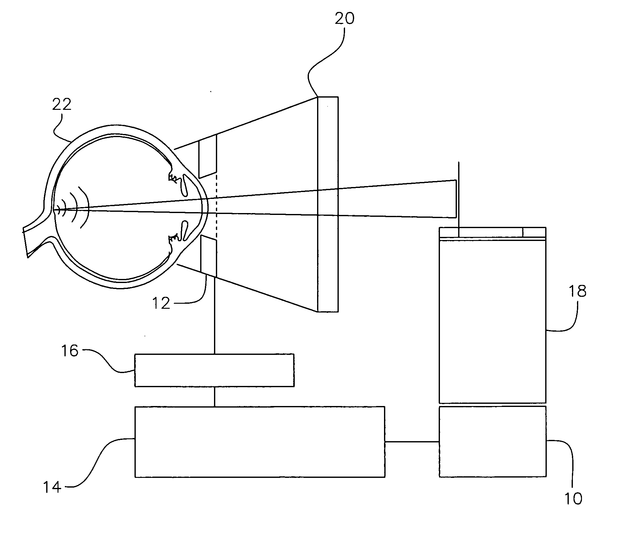
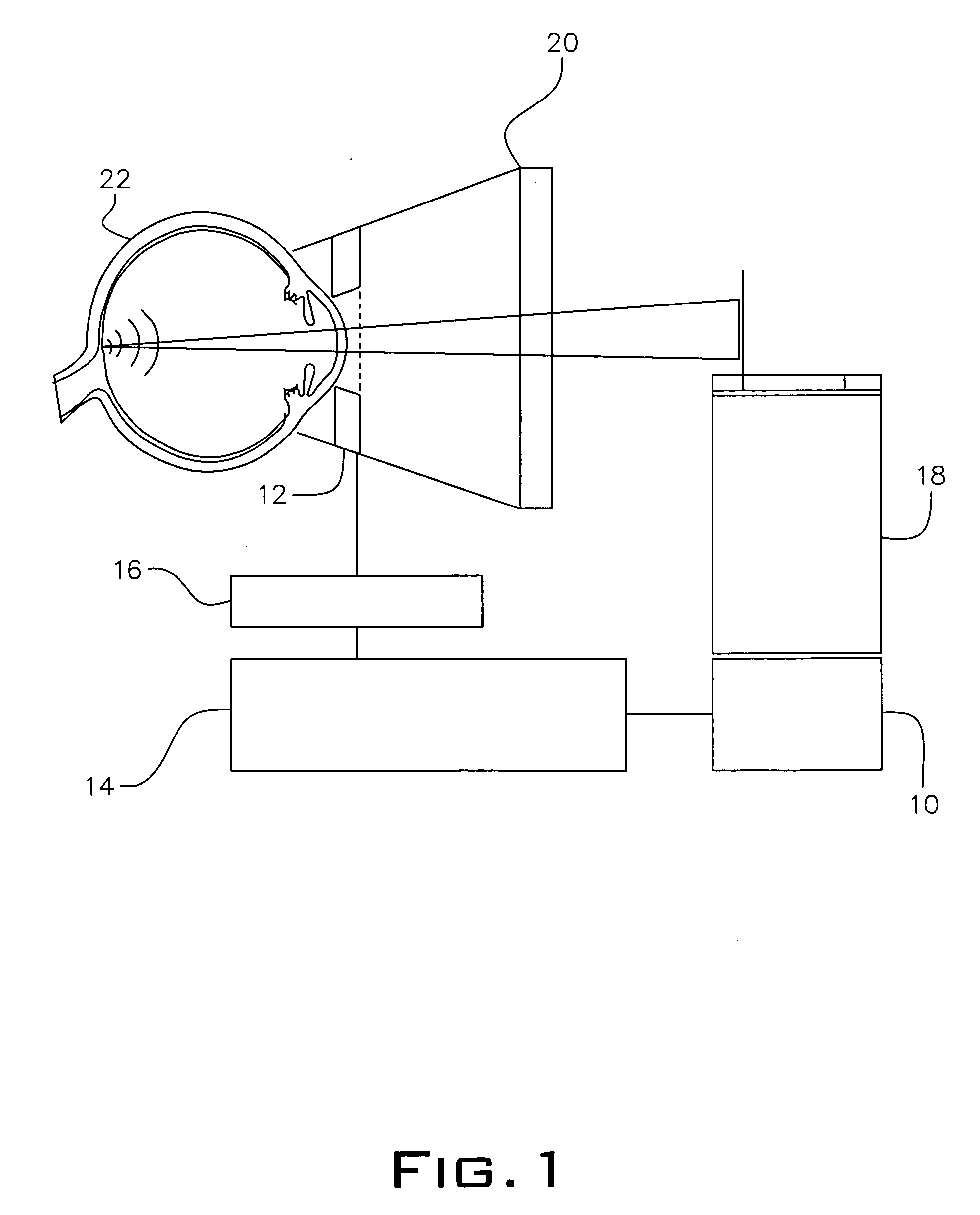
[0045]FIG. 1 is a survey sketch of an embodiment for an opto-acoustic measurement on an eye;

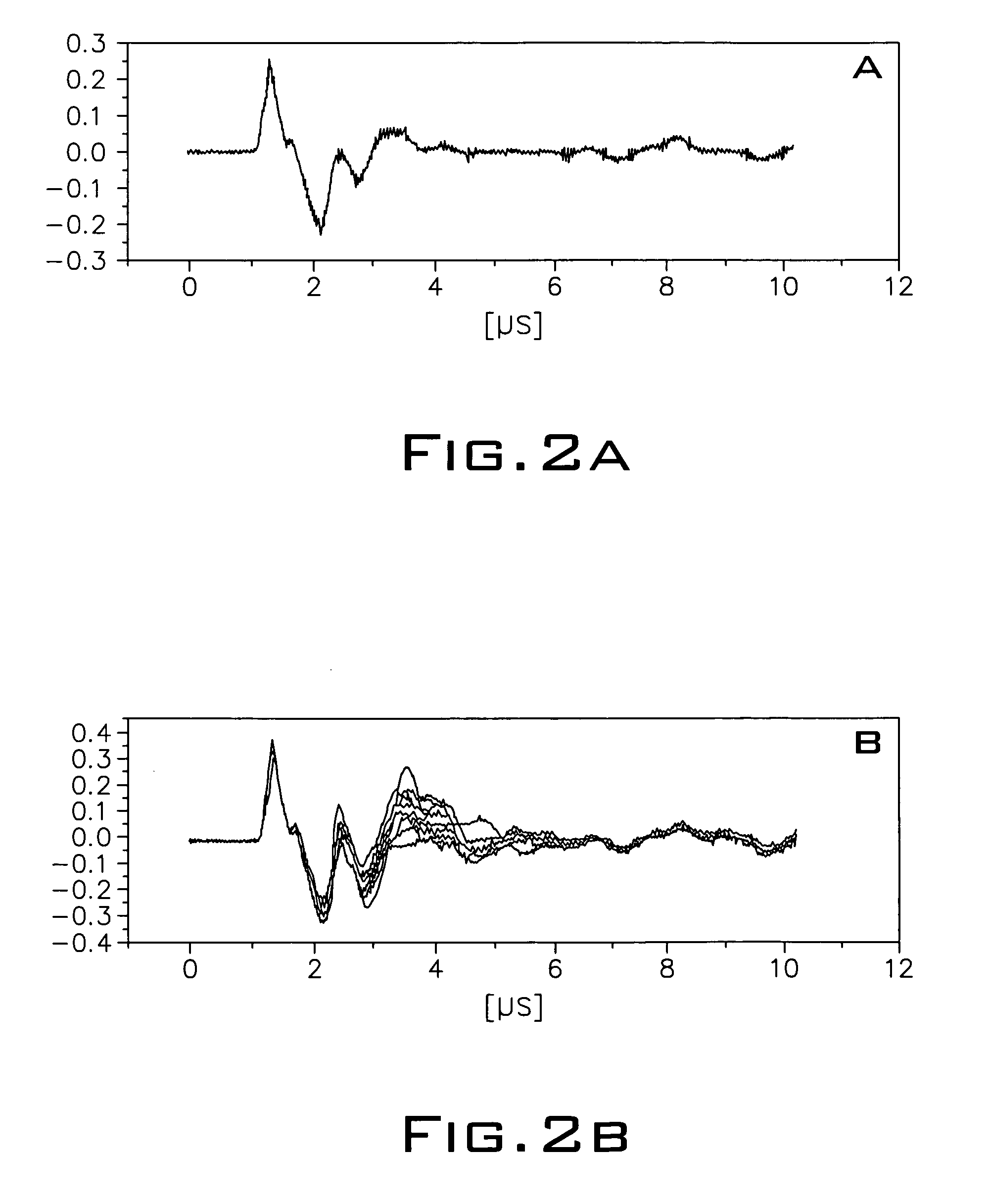
[0046]FIG. 2 is illustrates measurement results in a curve form wherein the superimposing of pressure transients of from pulse energy below a bubble formation threshold (A) and then pulse energy above a bubble formation threshold (B); time being plotted on the x axis and pressure being plotted in random units on the y axis (for both (A) and (B), thirty traces);

[0047]FIG. 3a shows an example for a rising pulse energy sequence until there is bubble formation detection;

[0048]FIG. 3b shows another example for a rising pulse energy sequence until there is bubble formation detection;

[0049]FIG. 3c shows an example of no further pulse energy rise once there has been bubble formation detection;

[0050]FIG. 3d shows an example of a reduced pulse energy sequence once there has been bubb...


PUM


Abstract

This invention relates to a method for operation of an irradiation laser whereby laser pulse sequences or pulses of varying length are modified during application such that the comparability of recorded transients is retained.

Description

PRIOR APPLICATIONS [0001] This US utility patent application is a continuation-in-part of PCT application number PCT / DE2004 / 001498, filed on Jul. 9, 2004 which bases priority on German application number DE 103 31 792.9, filed on Jul. 11, 2003.BACKGROUND OF THE INVENTION [0002] 1. Field of Invention [0003] The invention relates to a method for operating a laser. In particular, it relates to a method of operating a laser having dosimetry control for use in ophthalmic medicine, but also in general therapy of biological tissue. [0004] 2. Description of the Prior Art [0005] In ophthalmology, laser systems are widely used both in correcting visual acuity (e.g. corneal ablation) and also in the therapy of retinal diseases. Lasers work well for this purpose due to the transparency of the eye for visible light. [0006] Special interests exist in connection with the treatment of the dysfunction of “retinal pigmentary epithelium” (RPE), a highly pigmented monocellular layer between the choroid...

Claims


Application Information

Patent Timeline
Patent Type & Authority Applications(United States)
IPC IPC(8): A61B18/18A61N5/06A61B18/20A61F9/008
CPCA61B18/20A61B2018/00636A61F9/008A61F9/0084A61F2009/00844A61F2009/00863A61F2009/00897
Inventor BRINKMANN, RALPHSCHUELE, GEORG
Owner MEDIZINISCHES LASERZENTRUM LUEBECK GMBH
Why Eureka
Try Eureka