Semiconductor integrated circuit for controlling power supply, an electronic component and a power supply device
- Summary
- Abstract
- Description
- Claims
- Application Information
AI Technical Summary
Benefits of technology
Problems solved by technology
Method used
Image

Examples
second embodiment
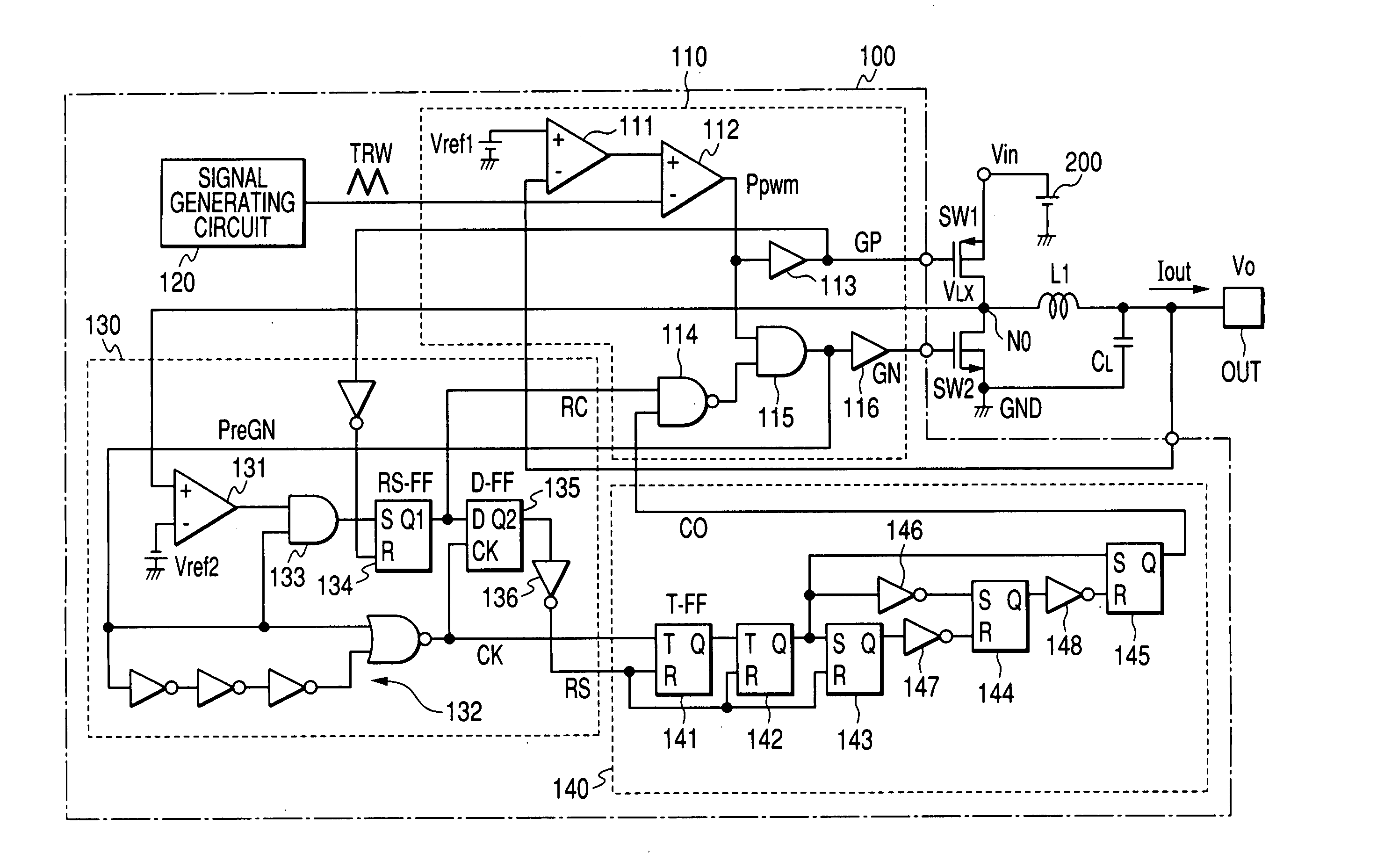
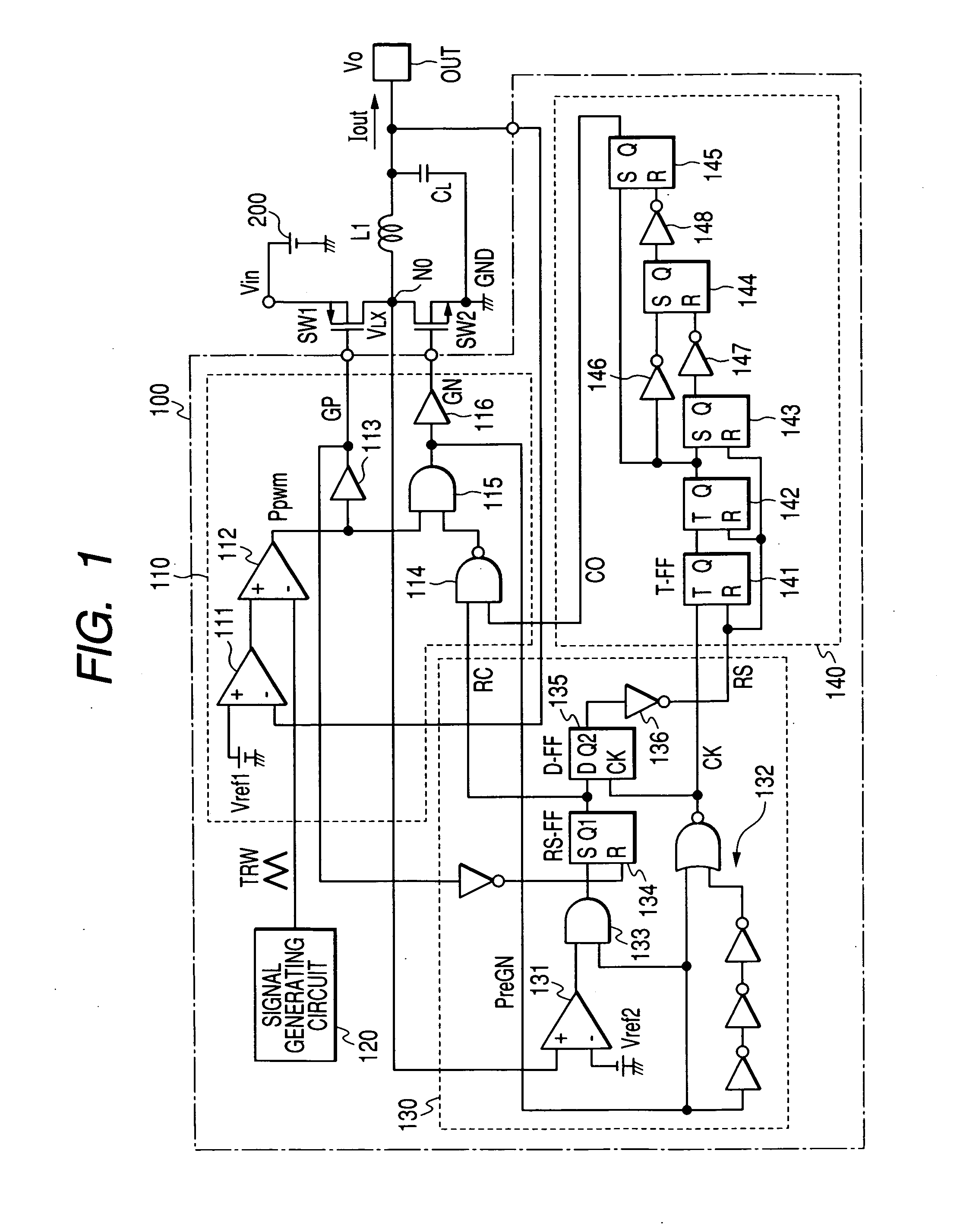
[0054]FIG. 3 shows a semiconductor integrated circuit for controlling power supply according to the present invention. In FIG. 3, the same circuits and devices as those in FIG. 1 are designated with the same reference numerals and their descriptions are omitted.
[0055] In the semiconductor integrated circuit for controlling power supply according to this embodiment, a time constant circuit (timer circuit) 140′ consisting of a resistor R1 and a capacitor C1 is provided instead of the counter circuit as the reverse current prevention holding circuit 140 in the first embodiment. This time constant circuit 140′ is designed as follows: when the reverse current detection circuit 130 (previous stage) detects a reverse current and output Q2 of the flip flop 135 (final step) goes high, charge is injected through the resistor R1 into the capacitor C1 and the potential of node N1 of connection of R1 and C1 gradually rises; when it exceeds a logical threshold for the NAND gate 114, output of the...
third embodiment
[0057]FIG. 4 shows a semiconductor integrated circuit for controlling power supply according to the present invention. In FIG. 4, the same circuits and devices as those in FIG. 1 are designated with the same reference numerals and their descriptions are omitted.
first embodiment
[0058] The semiconductor integrated circuit for controlling power supply according to this embodiment includes a variable voltage circuit 137 which makes reference voltage Vref2 of the reverse current detection comparator 131 in the first embodiment variable, and an overvoltage detection circuit 117 which consists of an error amplifier for detecting that the regulator's output voltage Vo becomes higher than a prescribed upper limit voltage Vref3, so that the reference voltage Vref2 changes when an overvoltage is detected. Concretely, if output voltage Vo becomes higher than the prescribed upper limit voltage, the reference voltage Vref2 is slightly increased so as to delay detection of a reverse current by the reverse current detection circuit 130 and allow some reverse current to flow through the low-side switching device SW2.
[0059] This makes it possible to draw the current in the coil toward the ground and make output voltage Vo closer to the target voltage quickly when output vo...
PUM
 Abstract
Description
Claims
Application Information
PatSnap Eureka turns technology decisions into work you can execute. Powered by our Innovation Knowledge Graph, it runs expert workflows across engineering, life sciences, materials and intellectual property. Get your review-ready output in minutes.


