Gas laser oscillator

a laser oscillator and laser technology, applied in the direction of lasers, gas laser construction details, laser details, etc., can solve the problems of difficult starting of discharge, increased discharge voltage at the time of discharge start, and damage to the gas in the laser, so as to prevent the occurrence of insulation breakdown in the discharge tube segments, prevent damage, and shorten the effect of tim

Inactive Publication Date: 2006-06-01
FANUC LTD
View PDF5 Cites 15 Cited by
  • Summary
  • Abstract
  • Description
  • Claims
  • Application Information

AI Technical Summary

Benefits of technology

[0019] That is, in the fifth aspect of the invention, by conducting a warmup operation by a laser gas pressure and discharge voltage different from those at the time of normal operation, the occurrence of insulation breakdown at the discharge tube segments is further prevented. Note that the laser gas pressure and discharge voltage at the time of warmup operation are preferably values smaller than the laser gas pressure and discharge voltage at the time of normal operation. This enables the warmup operation to be performed while avoiding insulation breakdown.
[0020] According to the above aspects of the invention, the effect is exhibited that the discharge tube can be prevented from being damaged by judging any abnormality in

Problems solved by technology

In such a case, the laser gas will have impurity molecules, that is, molecules of the lubrication oil, mixed into it and therefore the laser gas will deteriorate.
If operating a gas laser oscillator in the state with the laser gas deteriorated, the discharge will become hard to start and the discharge voltage at the time of start of discharge will rise greatly compared with when the laser gas is not deteriorated.
This rise in the discharge voltage may cause insulation breakdown to occur outside of the discharge tube and the discharge tube to be damaged.
In particular, in recent years, the outputs of laser oscillators have increased as a general tendency, so the possibility of discharge tubes being damaged has been rising.
However, whether laser gas has deteriorated must be judged by the operator himself, so ther

Method used


Image

  • Gas laser oscillator
  • Gas laser oscillator
  • Gas laser oscillator

Examples


Embodiment Construction

[0031] Below, the attached drawings will be referred to so as to explain embodiments of the present invention. In the following drawings, the same members are assigned the same reference numerals. To facilitate understanding, these drawings are suitably changed in scale.

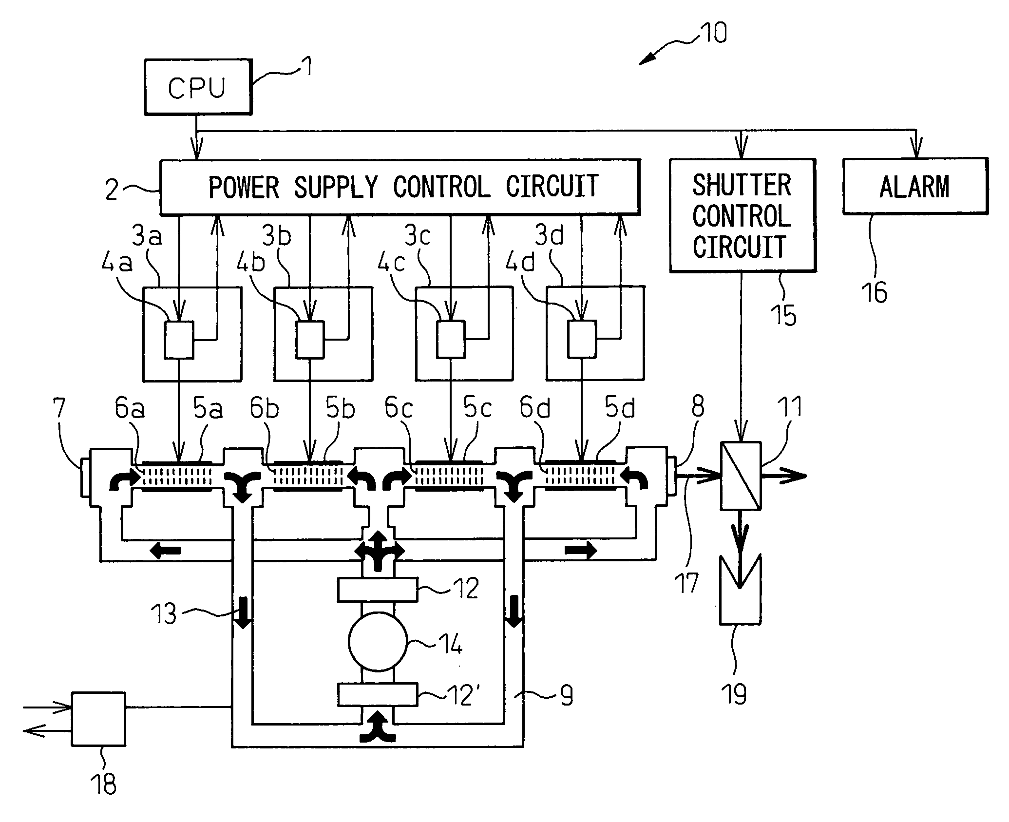
[0032]FIG. 1 is a schematic view of a gas laser oscillator according to the present invention. As shown in FIG. 1, the laser oscillator 10 is an induction discharge excitation type of gas laser oscillator and includes discharge tube segments 6a to 6d connected to a laser gas pressure control system 18. The laser gas pressure control system 18 can supply laser gas to the discharge tube segments 6a to 6d and exhaust the laser gas from the discharge tube segments 6a to 6d. As shown in FIG. 1, one end of the laser oscillator 10 is provided with a rear mirror 7 not having partial transmittance (mirror inside resonator), while the other end of the discharge tube 9 is provided with an output mirror 8 having partial transmi...


PUM


Abstract

A gas laser oscillator (10) provided with voltage detecting means (4a to 4d) for detecting the voltage of each of a plurality of discharge tube segments (6a to 6d) of a discharge tube before start of discharge and a discharge tube segment start judging means (1) for judging if each of the plurality of discharge tube segments (6a to 6d) has started based on the voltage of the discharge tube segments (6a to 6d) detected by the voltage detecting means (4a to 4d), wherein the discharge tube segment start judging means (1) allows all of the plurality of discharge tube segments (6a to 6d) to start only when the voltages of all of the discharge tube segments (6a to 6d) of the plurality of discharge tube segments are smaller than a predetermined voltage (Vb) is provided. Due to this, it is possible to judge an abnormality in the laser gas before the start of discharge without any work on the part of the operator and thereby prevent the discharge tube from being damaged.

Description

BACKGROUND OF THE INVENTION [0001] 1. Field of the Invention [0002] The present invention relates to a gas laser oscillator, more particularly relates to a gas laser oscillator used in a laser processing machine. [0003] 2. Description of the Related Art [0004] A general gas laser oscillator, for example, the gas laser oscillator disclosed in Japanese Unexamined Patent Publication No. 7-221378, excites laser gas sealed in a discharge tube by the discharge energy between discharge electrodes so as to emit a laser beam of an oscillation wavelength corresponding to the amount of energy discharged when the gas ions in the excited state return to the base state or the normal state. [0005] However, if stopping a gas laser oscillator for a long time, if the source (tank) of the laser gas supplied to the discharge tube is empty, if the inside of the gas laser oscillator is opened up to the atmosphere, etc., the lubrication oil of the blower used for circulating the laser gas in the discharge...

Claims


Application Information

Patent Timeline
IPC IPC(8): H01S3/03
CPCH01S3/036H01S3/073H01S3/09705
Inventor EGAWA, AKIRAANDO, MINORUMORI, ATSUSHI
Owner FANUC LTD
Why Eureka
Try Eureka