Hydraulic control circuit and method thereof

Active Publication Date: 2006-06-08
VOLVO CONSTR EQUIP
View PDF1 Cites 9 Cited by
  • Summary
  • Abstract
  • Description
  • Claims
  • Application Information

AI Technical Summary

Benefits of technology

[0025] It is, therefore, an object of the present invention to provide a hydraulic control circuit and method th

Problems solved by technology

However, a problem lies with the above-described related art technique.
In result, an overload is applied to the hydraulic pump 1.
At this time, different pressures are applied to the spool land surface, and this unbalance in the pressure generates a flow force inside the control valve 3.
According to the C-T2 diagram, even though a pilot signal pressure is inputted to the control valve, the spool does not move properly by the flow force, creating a stagnation.
However, if the operation state of the control valve spool corresponds to the C-T2 diagram by the application of flow force, a great flow force is generated when a large amount of press

Method used


Image

  • Hydraulic control circuit and method thereof
  • Hydraulic control circuit and method thereof
  • Hydraulic control circuit and method thereof

Examples


Embodiment Construction

[0042] A preferred embodiment of the present invention will be described herein below with reference to the accompanying drawings. In the following description, well-known functions or constructions are not described in detail since they would obscure the invention in unnecessary detail.

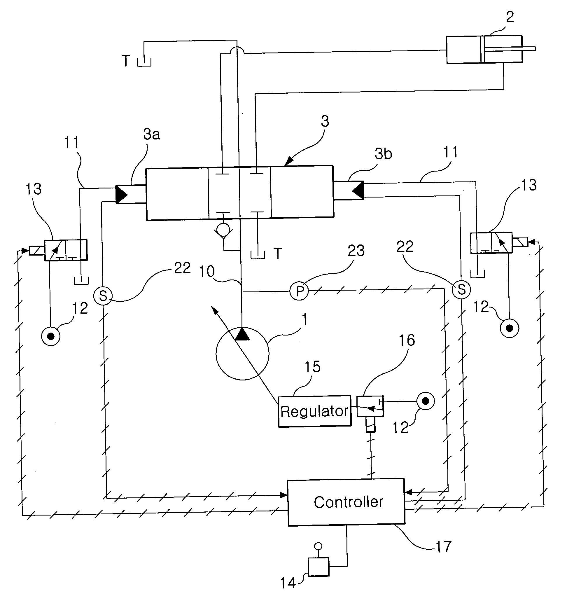
[0043]FIG. 6 is a schematic view of a hydraulic control circuit according to one embodiment of the present invention; and FIG. 7 is a schematic view illustrating a signal flow of a hydraulic control circuit according to one embodiment of the present invention.

[0044] The hydraulic control circuit of the present invention includes a hydraulic pump 1 for discharging a pressurized fluid, and a control valve 3 which drives a hydraulic cylinder 2 by supplying the pressurized fluid provided from the hydraulic pump 1 to the hydraulic cylinder 2 (which is an actuator) and exhausting the pressurized fluid from the hydraulic cylinder 2 to a reserve tank T.

[0045] The control valve 3 is installed on a supply l...


PUM


Abstract

Disclosed is a hydraulic control circuit and method thereof for reducing heat generation and energy losses caused by overload. The hydraulic control circuit of the present invention includes a control lever for generating a manipulated signal according to a manipulated variable; a control valve driven by a pilot signal pressure for controlling a flow of the pressurized fluid traveling from the hydraulic pump to the actuator; a displacement sensor for detecting a switching position of the control valve; a pump pressure sensor for detecting a pump pressure applied to the hydraulic pump; an electronic proportional valve for supplying a pilot signal pressure to the control valve; and a controller for receiving the manipulated signal, determining a pilot signal pressure, outputting a control signal to the electronic proportional valve, receiving signals from the displacement sensor and the pump pressure sensor and comparing the signals with pre-stored reference data, and outputting to the electronic proportional valve a stroke error correcting control signal for adjusting the switching position of the control valve.

Description

CROSS-REFERENCE TO RELATED APPLICATIONS [0001] This application claims benefit under 35 U.S.C. § 119 from Korean Patent Application No. 2004-102232, filed on Dec. 7, 2004, the entire content of which is incorporated herein by reference. BACKGROUND OF THE INVENTION [0002] 1. Field of the Invention [0003] The present invention relates in general to a hydraulic control circuit, more specifically, to a hydraulic control circuit for reducing heat generation and energy losses due to overload upon a hydraulic pump by adjusting switching position of a control valve through feedback control. [0004] 2. Description of the Related Art [0005] Heavy construction machinery and equipment such as an excavator uses a hydraulic control circuit for driving a work machine including a boom and an arm. The operation of the work machine is made possible through an actuator such as a hydraulic cylinder. In general, a constant flow of fluid is discharged from a hydraulic pump discharges and the pressurized f...

Claims


Application Information

Patent Timeline
IPC IPC(8): F15B11/10
CPCF15B11/0423F15B13/0433F15B19/005F15B21/087F15B2013/0409F15B2211/20546F15B2211/25F15B2211/3116F15B2211/3144F15B2211/329F15B2211/6309F15B2211/634F15B2211/665F15B2211/7053F15B2211/6316G05D16/20
Inventor KIM, JIN WOOK
Owner VOLVO CONSTR EQUIP
Why Eureka
Try Eureka