Process of maniudacturing dual-layered thermal insulation composite panel

a composite panel and dual-layer technology, applied in the direction of lamination, domestic applications, chemistry apparatus and processes, etc., can solve the problems of inability to molded constructional layers at once, insufficient high temperature mechanical strength, etc., to achieve high thermal insulation capability, high mechanical strength, and high temperature resistance

Inactive Publication Date: 2006-06-08
NAT CHUNG SHAN INST SCI & TECH
View PDF4 Cites 26 Cited by
  • Summary
  • Abstract
  • Description
  • Claims
  • Application Information

AI Technical Summary

Benefits of technology

[0007] It is therefore an object of the invention to provide a process of manufacturing a dual-layered thermal insulation composite panel satisfying requirements of high temperature resistance, high thermal insulation capability, high mechanical strength, and can be molded at once.

Problems solved by technology

However, it has been proved that asbestos are carcinogenic and thus production, transport, storage and demolish of asbestos are under strictly international control.
Although the interlayers of polyethylene and PU foam can reduce thermal conductance, they can only maintain approximately 100-150° C. Furthermore, these three-layered structures have not enough high temperature mechanical strength so that constructional layers cannot be molded at once.

Method used


Image

  • Process of maniudacturing dual-layered thermal insulation composite panel
  • Process of maniudacturing dual-layered thermal insulation composite panel
  • Process of maniudacturing dual-layered thermal insulation composite panel

Examples


example 1

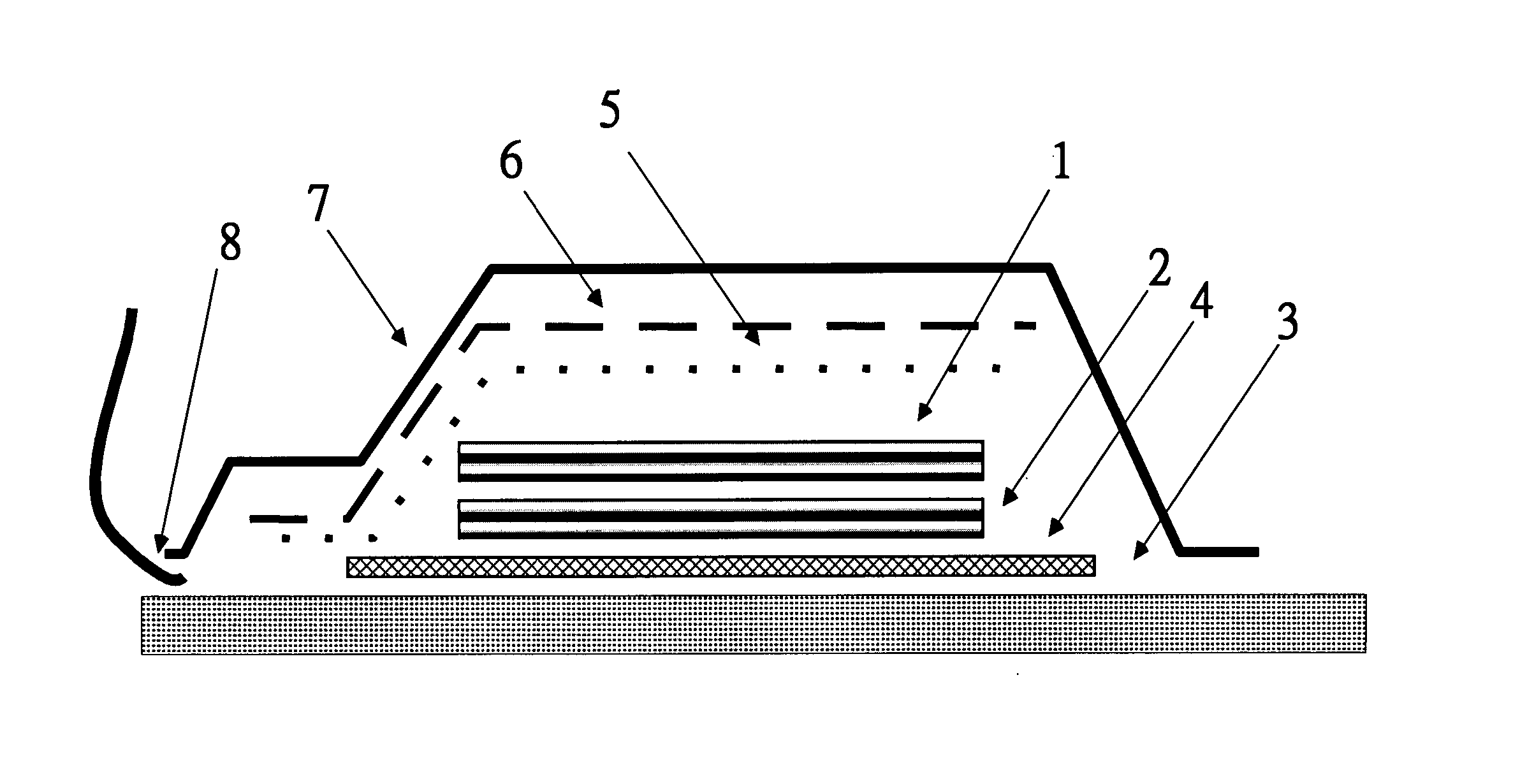
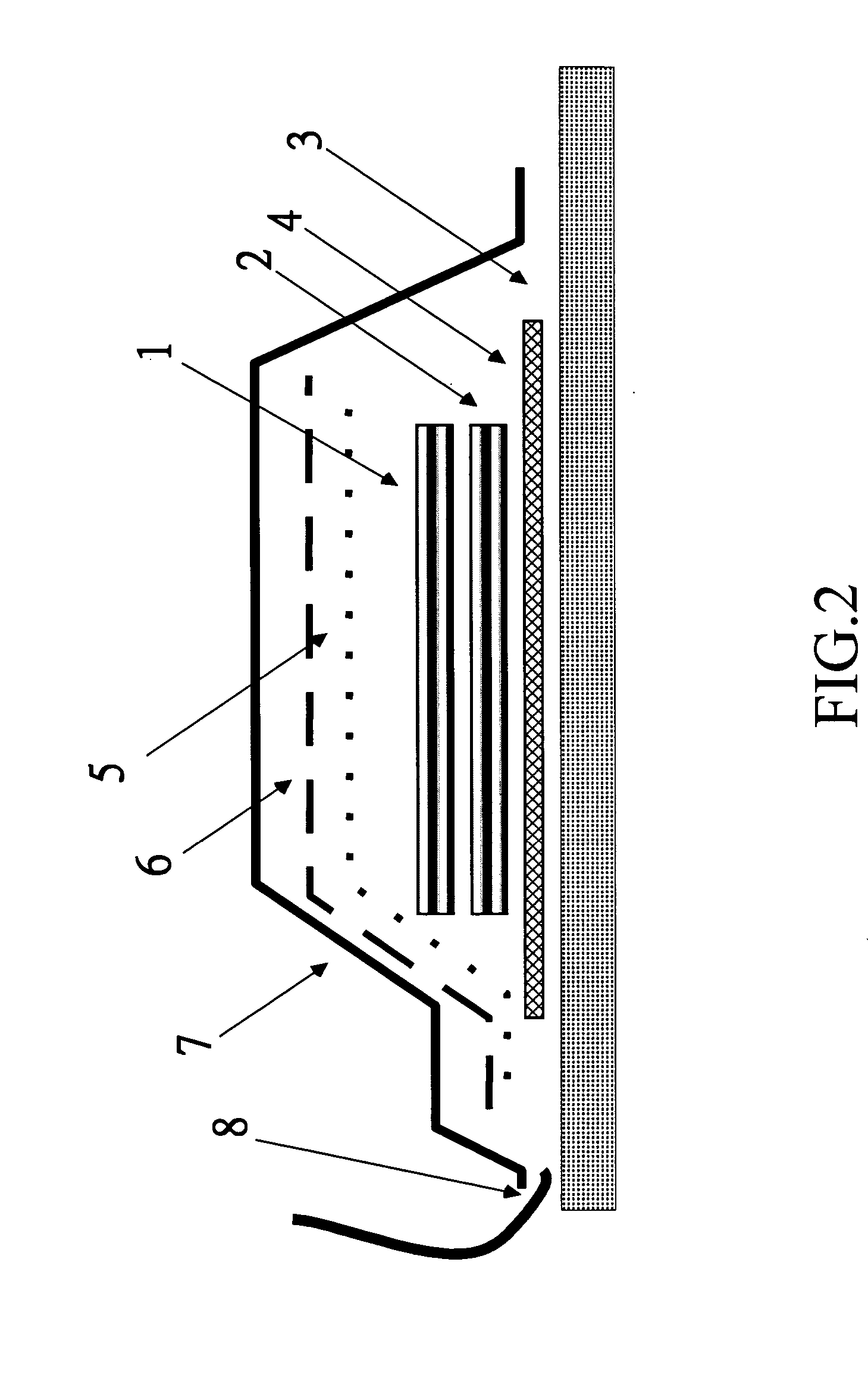
[0028] The outer layer includes 2 layers of carbon fiber reinforced phenolic resin composite, and the inner layer includes 10 layers of high-purity silica fiber reinforced phenolic resin composite. The autoclave is used in this example.

[0029] The 2 layers of carbon fiber reinforced phenolic resin prepregs, and the 10 layers of high-purity silica fiber reinforced phenolic resin prepregs are laminated on an aluminum alloy plate of 3 mm thickness that has an Airtech release film thereon already. A porous release film (Airtech A5000) having the same size of the laminate is applied over the laminate. Then, a polyester bleeder (Airweave SS-FR) is applied over the porous release film. The silicone sleeve (GE V240) and the vacuum valve are assembled therewith. The assembly is put into an autoclave. Then, a vacuum hose from the autoclave is connected to the vacuum valve. After the door of the autoclave is closed, vacuuming and heating with pressure are conducted. The assembly is molded in t...

example 2

[0032] The outer layer of 4 layers of carbon fiber (TTII G105) reinforced phenolic resin and the inner layer of 10 layers of high-purity silica fiber fabric with reinforced phenolic resin are laminated in turn on a flat mold. The flat mold has been coated with chromium, polished and applied with a release wax (CIBA Crown Wax) already. The inner layer and the outer layer are molded by three stages. The first stage is conducted by heating for 20 minutes at molding pressure of 2000 psi and temperature of 85° C. At the second stage, the temperature is firstly increased to 150° C. at a rate of 1.3° C. / min, then kept at 150° C. for 4 hours. The last stage is cooling. Thereafter, the panel is removed from the mold and cut into an appropriate size by a machine. The obtained panel has 2 mm-thick PAN-based carbon fiber reinforced phenolic resin composite and the 6 mm-thick high-purity silica fiber phenolic resin composite. The panel is subjected to 2700° C. flame jet of a rocket for 2 seconds...


PUM

PropertyMeasurementUnit
temperatureaaaaaaaaaa

Abstract

A dual-layered thermal insulation composite panel includes an out layer of high-temperature resistant carbon fiber reinforced phenolic resin composite and an inner layer of low thermal conductivity and high-purity silica fiber reinforced phenolic resin composite. A hot press or autoclave may be used to pressurize said materials into shaping. The dual-layered thermal insulation composite panel achieves excellent performance in thermal resistance, thermal insulation and mechanical strength.

Description

BACKGROUND OF THE INVENTION [0001] 1. Field of Invention [0002] The present invention relates to a process of manufacturing dual-layered thermal insulation composite panel. [0003] 2. Related Art [0004] Thermal insulation panels are well used in metal molds, thermal press and injection molding machines for thermal insulation from electrical or steam heat source. They are also applied in defense technology such as missile heat shields, rocket propulsion and launching system for thermal insulation at high temperature. Asbestos has been the most popular thermal insulation material among others, due to its naturally unfailing supply, good process ability and insulation effect. However, it has been proved that asbestos are carcinogenic and thus production, transport, storage and demolish of asbestos are under strictly international control. Therefore, a substitute material for asbestos has been eagerly developed. [0005] U.S. Pat. No. 5,683,799 discloses a thermal insulation panel which is...

Claims


Application Information

Patent Timeline
Patent Type & Authority Applications(United States)
IPC IPC(8): B29C70/44
CPCB29C70/08B29C70/44B29K2061/04B29K2709/00B29K2995/0015B29L2031/3097
Inventor CHANG, GENG-WENHUANG, MAU-YIGER, GUANG-SHYANGCHEN, JOHN-CHANG
Owner NAT CHUNG SHAN INST SCI & TECH
Why Eureka
Try Eureka