Controlled densification of fusible powders in laser sintering

Active Publication Date: 2006-06-08
3D SYST INC
View PDF9 Cites 89 Cited by
  • Summary
  • Abstract
  • Description
  • Claims
  • Application Information

AI Technical Summary

Benefits of technology

[0011] The invention provides an improved method of forming a three dimensional object using laser sintering and an apparatus for accomplishing the method. Each powder layer is scanned a plurality of times with a laser along the same fusion path without significant cooling between the scans so that the powder in the fusion path remains at or near the melting point without extending outside the fusion boundary and without fusing powder outside the part boundary. Density and tensile strength, tensile modulus, a

Problems solved by technology

Nevertheless, laser sintered parts are sometimes dimensionally distorted and may not have the strength of, for example, injection molded plastic parts.
The sintering process may leave void spaces between the individual partic

Method used


Image

  • Controlled densification of fusible powders in laser sintering
  • Controlled densification of fusible powders in laser sintering
  • Controlled densification of fusible powders in laser sintering

Examples


examples

[0049] The following Examples are for illustrative purposes only and should not be considered limiting in any way.

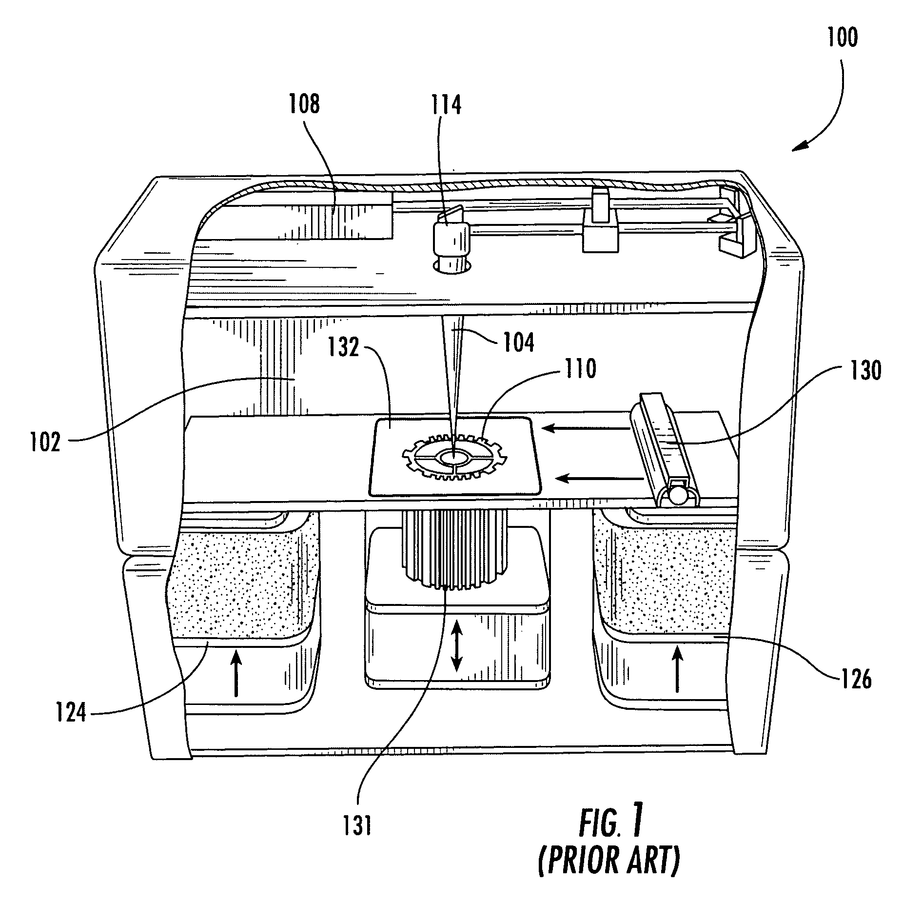
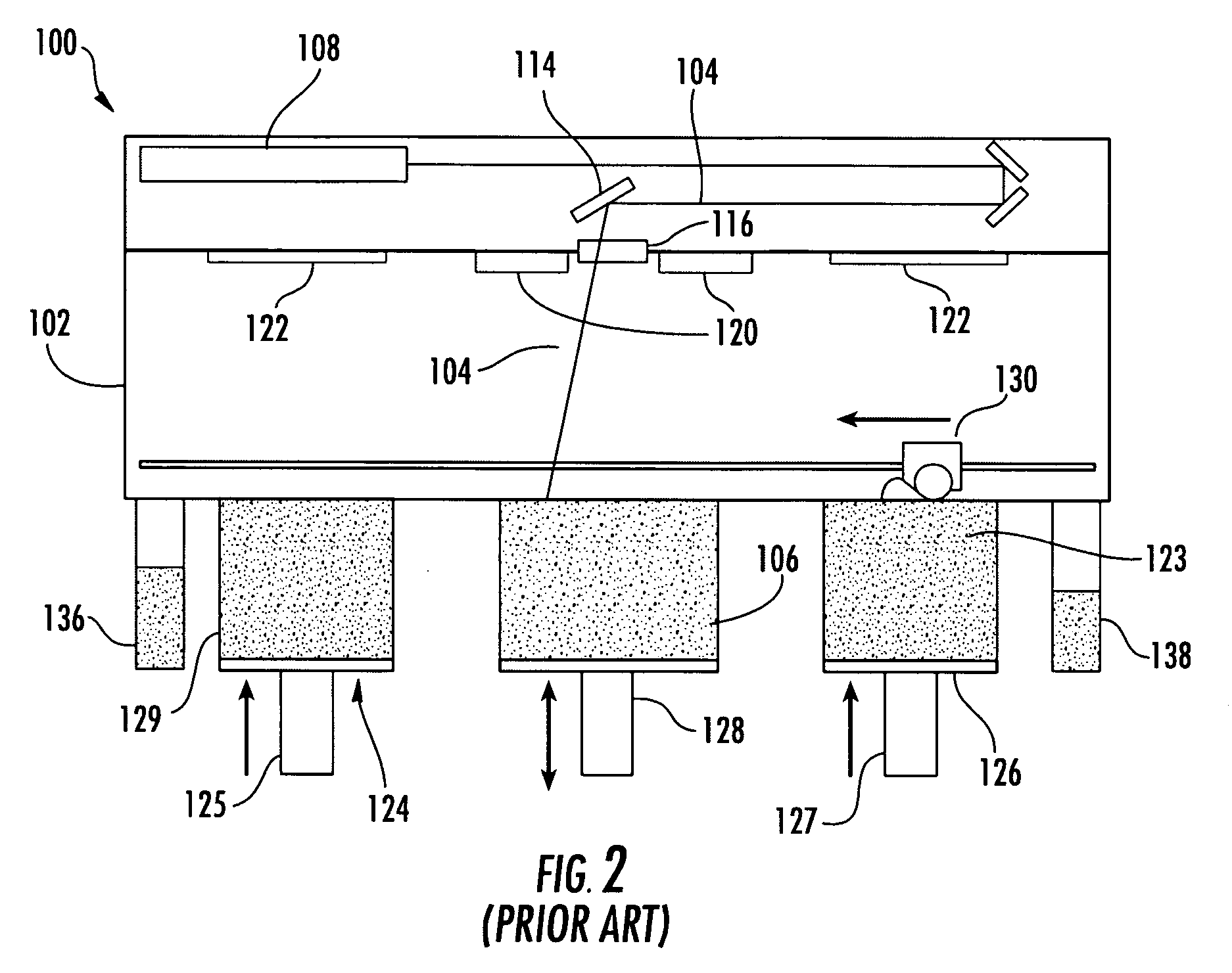
[0050] In the following examples, the samples were prepared by sintering a layer of DuraForm® nylon powder with from 1 to 3 scans at varying laser intensities. A 100 watt high speed Vanguard™ V207 laser sintering system available from 3D Systems, Inc. was used to form the samples.

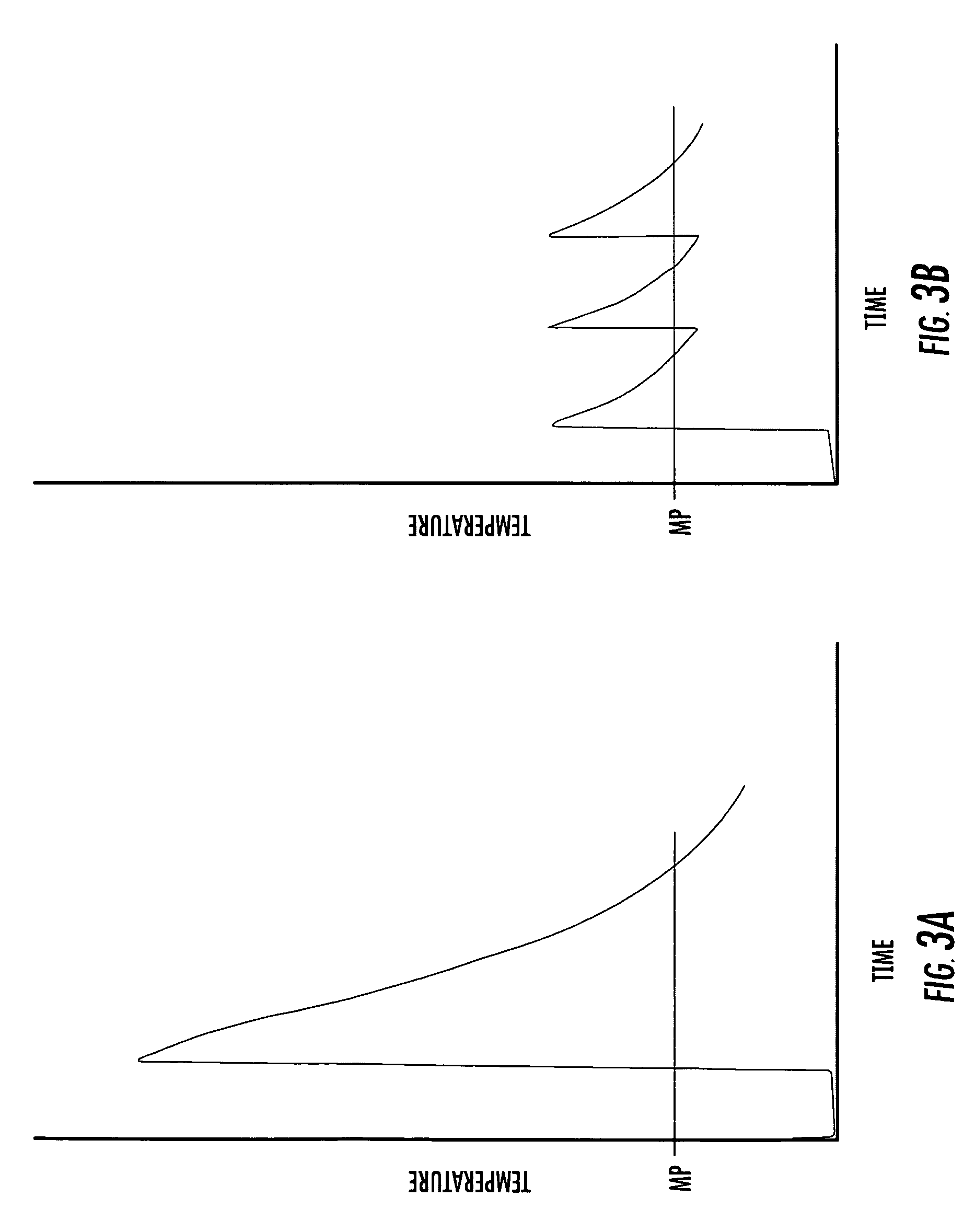
[0051] For convenience, the examples in Table 1 below illustrate multiple scans of equal low power. In some cases, the examples show relative tensile elongation improvements of 100% or better compared to a conventional single scan technique (column for 1 scan in Table 1) and improvements of approximately 30% in elongation compared to elongations of approximately 10% for the conventional technique.

[0052] It should be recognized that multiple scans at too high a power will result in growth, as shown above in Table 1 for the example of 10 scans at 7 watts.

[0053] Multiple scanning is desirably a...


PUM

PropertyMeasurementUnit
Thicknessaaaaaaaaaa
Massaaaaaaaaaa
Areaaaaaaaaaaa

Abstract

The invention relates to a method producing parts using laser sintering wherein a fusible powder is exposed to a plurality of laser scans at controlled energy levels and for time periods to melt and densify the powder and in the substantial absence of particle bonding outside the fusion boundary. Strength is improved up to 100% compared to previous methods. An example includes a relatively high energy initial scan to melt the powder followed by lower energy scans controlled to densify the melt and separated in time to dissipate heat to the surrounding part cake. The rate and extent to which the powder particles are fused together can be controlled so that each successive scan can be used to fuse the particles together in discreet incremental steps. As a result, the final dimensions of the part and its density and mechanical properties can be improved compared to conventional methods and part growth avoided.

Description

BACKGROUND OF THE INVENTION [0001] The invention relates generally to a method of rapid prototyping and manufacturing and, more particularly, to laser sintering. [0002] Rapid prototyping and manufacturing (RP&M) is the name given to a field of technologies that can be used to form three-dimensional objects rapidly and automatically from computer data representing the objects. In general, rapid prototyping and manufacturing techniques build three-dimensional objects, layer-by-layer, from a working medium utilizing sliced data sets representing cross-sections of the object to be formed. Typically an object representation is initially provided by a Computer Aided Design (CAD) system. RP&M techniques are sometimes referred to as solid imaging and include stereolithography, ink jet printing as applied to solid imaging. and laser sintering, to which the invention is directed. [0003] Laser sintering apparatus dispenses a thin layer of fusible powder, often a fusible polymer powder or polym...

Claims


Application Information

Patent Timeline
IPC IPC(8): B29C35/08B29C41/02B29C67/00C23C24/10C23C26/02
CPCB29C67/0077C23C24/10C23C26/02B29C64/153B33Y10/00B33Y70/00
Inventor RUATTA, STEPHEN A.MOUSSA, KHALIL M.
Owner 3D SYST INC
Why Eureka
Try Eureka