Multi-frequency clock synthesizer

Active Publication Date: 2006-06-08
SKYWORKS SOLUTIONS INC
View PDF98 Cites 46 Cited by
  • Summary
  • Abstract
  • Description
  • Claims
  • Application Information

AI Technical Summary

Benefits of technology

[0011] It would also be desirable to provide a clock source that meets accuracy requirements, allows the use of a resonator that i

Problems solved by technology

However, resonators typically have a limited optimum range due to manufacturing constraints.
That is, it is hard to pull a crystal over a wide range.
However, various applications have requirements for numerous frequencies outside the easy range for a resonator.
The drive to design network equipment with multi-service capable interfaces has dramatically increased the complexity of the timing subsystems.
The design of these PLLs is difficult because they must provide non-integer clock scaling, operate at high frequencies (>600 MHz), provide low jitter (<0.3 ps RMS), and cover a range of frequencies tha

Method used


Image

  • Multi-frequency clock synthesizer
  • Multi-frequency clock synthesizer
  • Multi-frequency clock synthesizer

Examples


Embodiment Construction

)

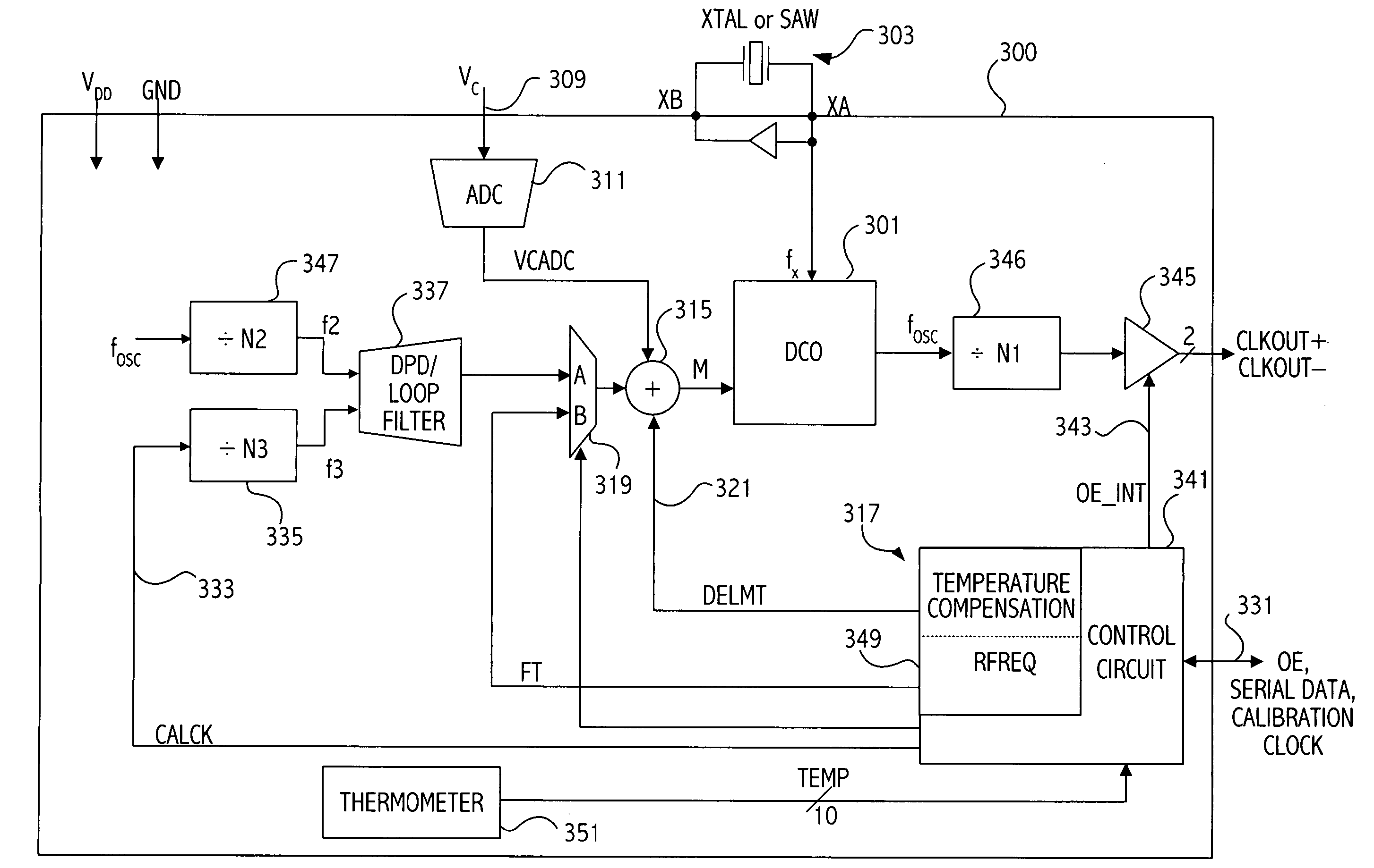
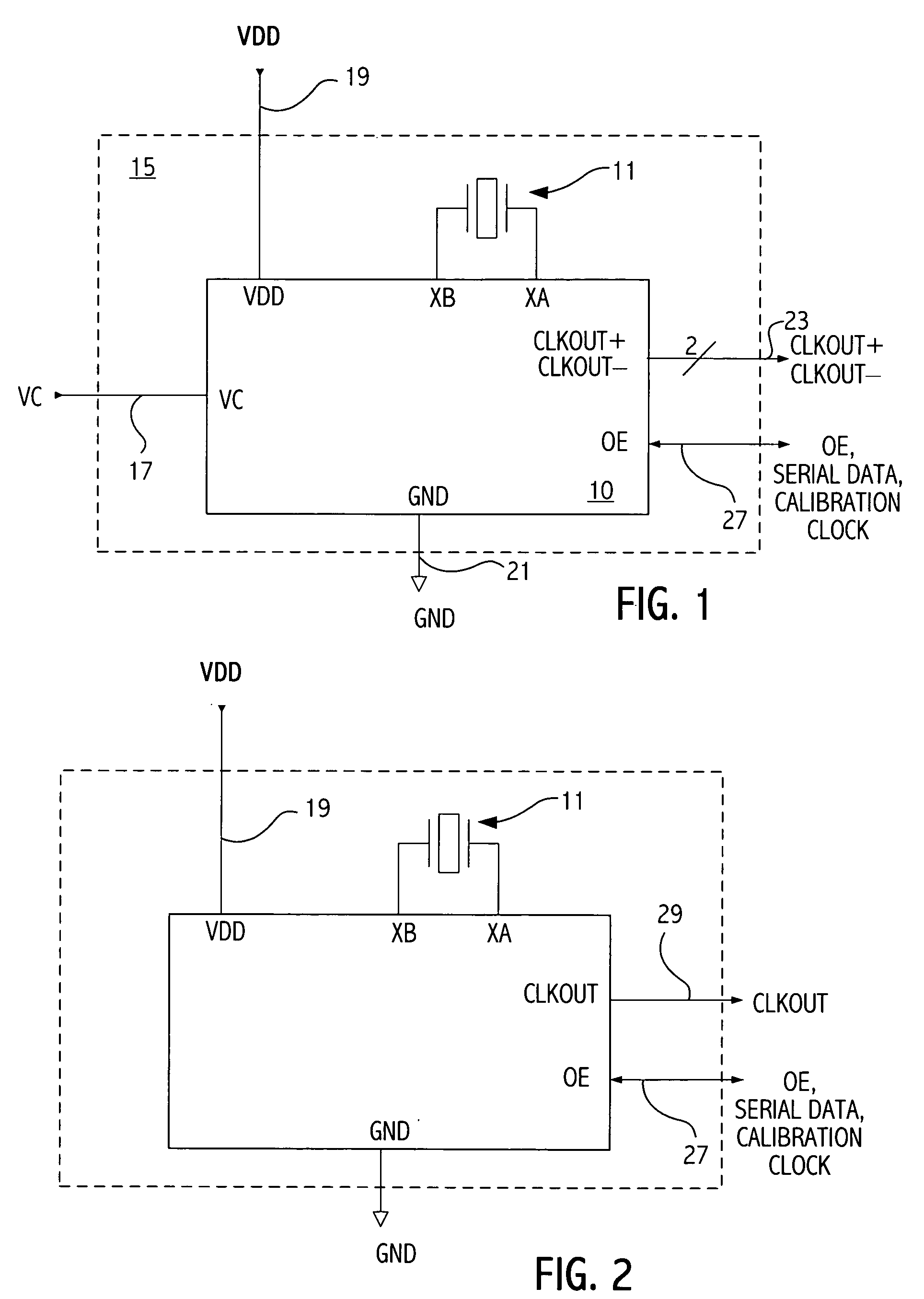
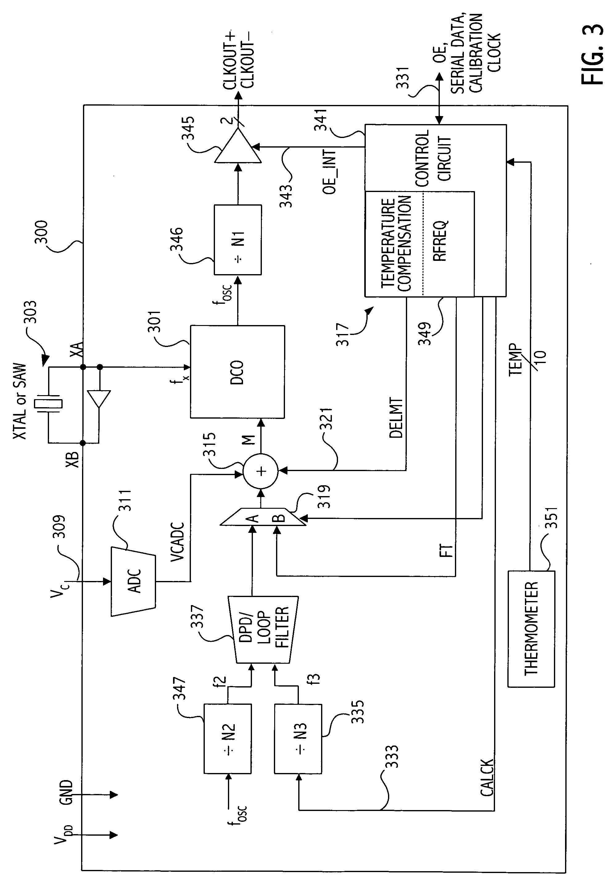
[0037] Referring to FIG. 1, a high level diagram shows a clock source device that includes an integrated circuit 10 coupled to a crystal 11. In one embodiment both the integrated circuit 10 and the crystal 11 are packaged in a standard ceramic package 15 that is typically utilized for packaging a voltage controlled crystal oscillator (VCXO). Note that another resonating device such as a surface acoustic wave (SAW) resonator may be utilized in place of crystal 11. In the illustrated embodiment, the package 15 includes standard input / output signals including a voltage control input 17, a power and ground input, 19 and 21 respectively, differential clock outputs and an output enable (OE) pin 27. FIG. 2 illustrates a four pin XO package implementation in which the control voltage input 17 is not utilized and the output clock 29 is single ended. A six pin XO package configuration may also be utilized in which the control voltage input on the package is not connected when the package 15 ...


PUM


Abstract

A phase-locked loop (PLL) circuit includes an input for receiving a timing reference signal, a phase detector circuit coupled to receive the timing reference signal, a controllable oscillator circuit controlled according to an output of the phase detector circuit, and a feedback divider circuit having an output coupled to the phase detector and an input coupled to the controllable oscillator circuit. The phase-locked loop circuit is coupled to output one of a plurality of output signals having an arbitrary frequency relationship to each other according to a frequency selection mechanism, the frequency selection mechanism including one or more input terminals coupled to control a divide ratio of the feedback divider circuit. The frequency selection mechanism selects one of a plurality of stored values. The selected stored value controls, at least in part, a divide ratio of the feedback divider circuit, thereby providing a pin programmable device capable of selecting among output frequencies having an arbitrary relationship to each other.

Description

[0001] This application is a continuation in part of application Ser. No. 10 / 878,218, filed Jun. 28, 2004, which application claims benefit under 35 U.S.C. 119(e) of application 60 / 567,479, entitled “METHOD AND APPARATUS FOR A PROGRAMMABLE CLOCK SOURCE GENERATING A WIDE RANGE OF OUTPUT FREQUENCIES,” filed May 3, 2004, naming Axel Thomsen, Yunteng Huang, Jerrell P. Hein as inventors, and which application is a continuation-in-part of application Ser. No. 10 / 675,543, entitled “CALIBRATION OF OSCILLATOR DEVICES,” filed Sep. 30, 2003, naming Jerrell Hein and Axel Thomsen as inventors, which claimed benefit under 35 U.S.C. § 119(e) of application 60 / 467,813, filed May 2, 2003; which applications are incorporated herein by reference.BACKGROUND [0002] 1. Field of the Invention [0003] This application relates to integrated circuit devices more particularly to integrated circuits utilized in generating clock signals and systems incorporating such circuits. [0004] 2. Description of the Relate...

Claims


Application Information

Patent Timeline
IPC IPC(8): H03B21/00
CPCH03L7/0898H03L7/197H03L7/1976H03L7/23
Inventor THOMSEN, AXELHUANG, YUNTENGHEIN, JERRELL P.PETROWSKI, MICHAEL III
Owner SKYWORKS SOLUTIONS INC
Why Eureka
Try Eureka