Display device, driving method thereof and electronic appliance

Inactive Publication Date: 2006-06-08
SEMICON ENERGY LAB CO LTD
View PDF52 Cites 23 Cited by
  • Summary
  • Abstract
  • Description
  • Claims
  • Application Information

AI Technical Summary

Benefits of technology

[0024] According to the invention, in performing a digital time gray scale method in an active matrix display device, a reset operation is not required; therefore, both the aperture ratio and

Problems solved by technology

The aforementioned problem derives from the fact that there is a case where the time required for data writing to the

Method used


Image

  • Display device, driving method thereof and electronic appliance
  • Display device, driving method thereof and electronic appliance
  • Display device, driving method thereof and electronic appliance

Examples


embodiment 1

[0052] This embodiment illustrates a configuration example of an active matrix display device of the invention and an example of an electronic appliance having the display device as a display portion.

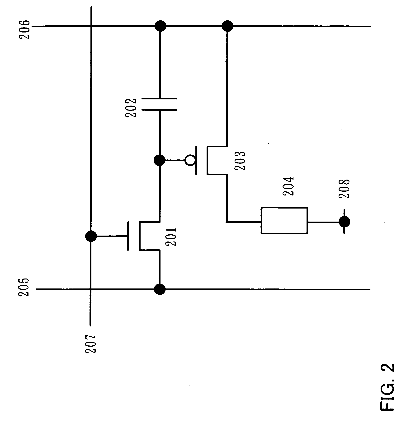
[0053]FIG. 2 shows a configuration example of a pixel. The pixel includes a switching transistor 201, a capacitor 202, a driving transistor 203, a display element 204, a data line 205, a power source line 206 and a scan line 207.

[0054] A gate terminal of the switching transistor 201 is connected to the scan line 207 and a first terminal (source terminal or drain terminal) thereof is connected to the data line 205 while a second terminal thereof (source terminal or drain terminal) thereof is connected to the power source line 206 through a gate terminal of the driving transistor 203 and the capacitor 202. A first terminal (source terminal or drain terminal) of the driving transistor 203 is connected to the power source line 206 while a second terminal (source terminal or drain terminal...

embodiment 2

[0084] Description is made with reference to the drawings on one configuration example of a display device described in Embodiment 1.

[0085] A pixel 410 shown in FIG. 5 has a configuration where two transistors are provided. The pixel 410 is provided in a region where a data line Dx (x is a natural number, 1=x=m) intersects a scan line Gy (y is a natural number, 1=y=n) with an insulating layer interposed therebetween. The pixel 410 includes an EL element 405, a capacitor 407, a switching transistor 406 and a driving transistor 404. The switching transistor 406 controls a video signal input while the driving transistor 404 controls the light-emission and non-light-emission of the EL element 405. These transistors are field effect transistors, and for example, thin film transistors may be employed.

[0086] A gate of the switching transistor 406 is connected to the scan line Gy and one of a source and drain thereof is connected to the data line Dx while the other is connected to a gate ...

embodiment 3

[0098] Description is made on a panel corresponding to one mode of a display device of the invention, on which a pixel array 411, a scan line driver circuit 408 and a data line driver circuit 409 are mounted. Over the substrate 450, the pixel array 411 having multiple pixels each including the EL element 405, the scan line driver circuit 408, the data line driver circuit 409 and a connection film 467 are provided (see FIG. 8A). The connection film 467 is connected to an external circuit.

[0099]FIG. 8B is a cross-sectional view along a line A-B of the panel in FIG. 8A, which shows the driving transistor 404, the EL element 405 and the capacitor 407 provided in the pixel array 411 and transistors provided in the data line driver circuit 409. A sealant 464 is provided around the pixel array 411, the scan line driver circuit 408 and the data line driver circuit 409, and the EL element 405 is sealed with the sealant 464 and a counter substrate 466. This sealing process is performed to pr...


PUM


Abstract

A driving method of a display device for expressing gray scales by a time gray scale method is provided where one frame is divided into multiple sub-frames, so that both the aperture ratio and the duty ratio can be maintained high while the power consumption can be suppressed low. The order of sub-frames is set to be different for each group having multiple pixel rows, and a data writing period of each group having the multiple pixel rows is set to be shorter than a data holding period of a sub-frame which corresponds to the least significant bit. While pixel rows belonging to a certain group are scanned, pixel rows belonging to the other groups are all in the data holding period. Accordingly, the driving frequency of data lines can be suppressed low and the power consumption can be reduced.

Description

BACKGROUND OF THE INVENTION [0001] 1. Field of the Invention [0002] The present invention relates to an active matrix display device and a driving method thereof. In addition, the invention relates to an electronic appliance having the display device as a display portion. [0003] 2. Description of the Related Art [0004] In order to perform multi-gray scale display using display elements, gray scales are required to be expressed by appropriately controlling the elements by means of a physical value. For example, if a liquid crystal element is used as the display element, gray scales are expressed by applying an analog voltage to the element. On the other hand, if an organic EL element is used as the display element, gray scales are expressed by supplying an analog current to the organic EL element. However, methods utilizing an analog value have limitations on the display accuracy. In particular, in an active matrix display device using organic EL elements which have been actively dev...

Claims


Application Information

Patent Timeline
IPC IPC(8): G09G3/30
CPCG09G3/2022G09G3/3258G09G3/3291G09G2300/0842H01L27/3244H10K59/12
Inventor KAWAE, DAISUKE
Owner SEMICON ENERGY LAB CO LTD
Why Eureka
Try Eureka