System and method for reducing power consumption during extended refresh periods of dynamic random access memory devices

a dynamic random access and memory device technology, applied in static storage, information storage, digital storage, etc., can solve the problems of constant refresh of memory cells, consuming power refreshing dram memory cells at a substantial rate, so as to reduce the leakage current and reduce the refresh rate

Active Publication Date: 2006-06-08
MICRON TECH INC
View PDF23 Cites 78 Cited by
  • Summary
  • Abstract
  • Description
  • Claims
  • Application Information

AI Technical Summary

Benefits of technology

[0012] A system and method of refreshing memory cells in an array allows refresh to occur in a normal refresh mode or in a static refresh mode, such as a self-refresh mode. In the normal refresh mode, a cell plate for the array is biased to a first voltage, such as one-half a supply voltage. The cell plate is also biased to the first voltage in the static refresh mode when the memory cells are being refreshed, which preferably occurs in a burst manner. However, the cell plate is biased to a second voltage in the static refresh mode when the memory cells are not being refreshed. This second voltage reduces the voltage between the source / drain of access transistors for the memory cells and the substrate, thereby reducing leakage current from memory cell capacitors. As a result, a reduced refresh rate can be achieved.

Problems solved by technology

However, DRAM devices have the disadvantage that their memory cells must be continually refreshed because of the means by which they store data.
Refreshing DRAM memory cells tends to consume power at a substantial rate.
Each time a row of memory cells is refreshed, a pair of digit lines for each memory cell are switched to complementary voltages and then equilibrated, which consumes a significant amount power.
If the required refresh rate for a DRAM device could be reduced, so also could the refresh power consumption.
The result is an erroneous reading of the memory cell 100 known as a data retention error.
As a result, the memory cell capacitor 114 must be frequently refreshed, thereby causing a DRAM device containing the memory cell capacitor 114 to consume substantial power.

Method used


Image

  • System and method for reducing power consumption during extended refresh periods of dynamic random access memory devices
  • System and method for reducing power consumption during extended refresh periods of dynamic random access memory devices
  • System and method for reducing power consumption during extended refresh periods of dynamic random access memory devices

Examples


Embodiment Construction

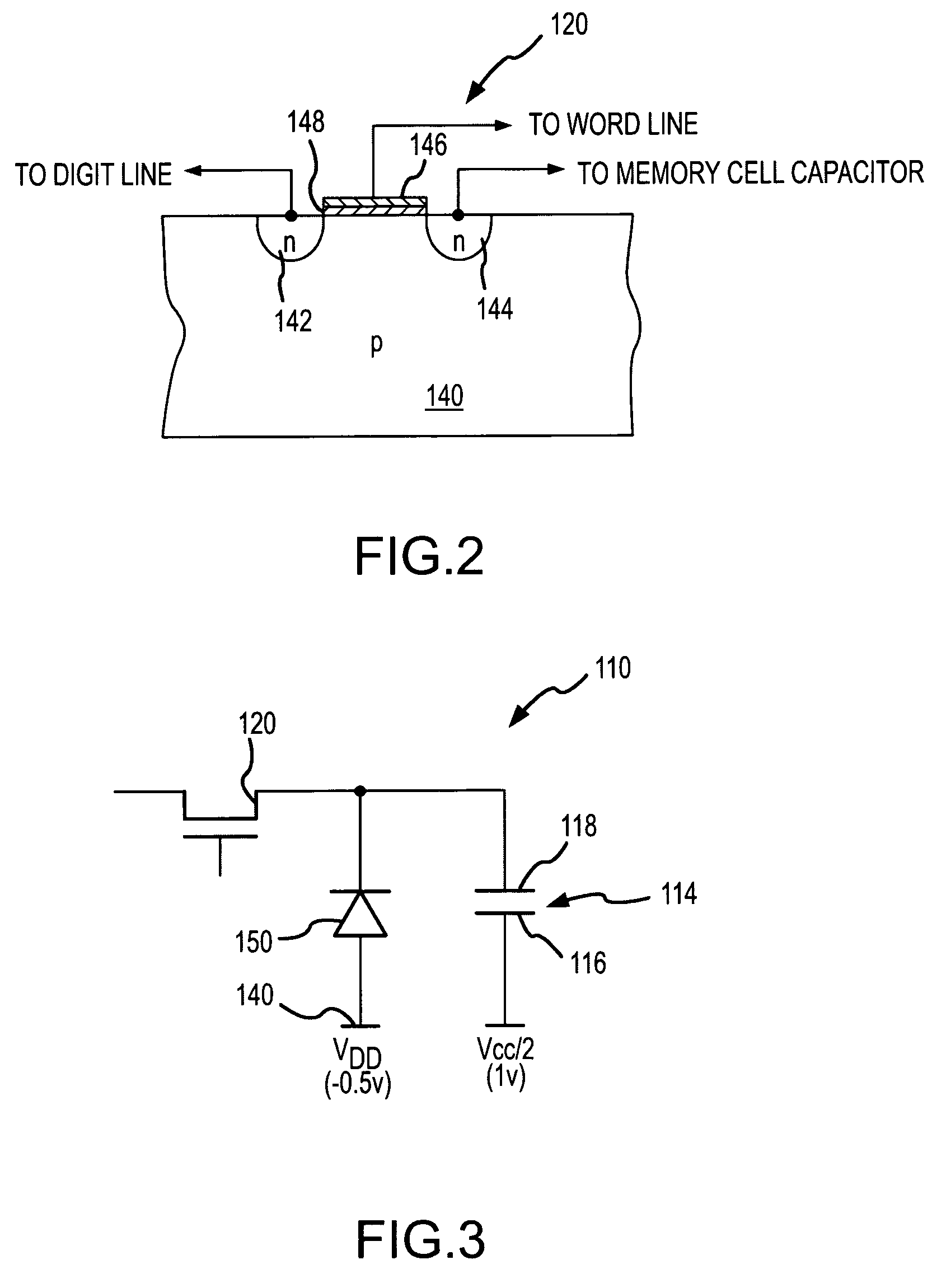
[0022] The principal of the operation of one embodiment of the invention is exemplified by the memory cell 110 shown in FIG. 4, which contains the access transistor 120, the memory cell capacitor 114 and the diode junction 150. As shown in FIG. 4, the memory cell capacitor 114 is initially charged to VCC, which is, in this example, 2 V. As previously explained, this condition places 2.5 V across the diode junction 150 is it results in substantial leakage from the memory cell capacitor 114. According to one embodiment of the invention, when a DRAM containing the memory cell 110 shown in FIG. 4 is to operate in a self-refresh mode, the DRAM reduces the bias voltage on the cell plate 116 from VCC / 2 to a lesser voltage VCC / 2−ΔV, which, in this example, is a change in voltage from 1V to 0.5V. When the voltage on the cell plate 116 is reduced by ΔV, the voltage on the other plate 118 of the memory cell capacitor 114 is also reduced by ΔV, which, in this example, reduces the voltage to 1.5...


PUM


Abstract

A dynamic random access memory (“DRAM”) device is operable in either a normal refresh mode or a static refresh mode, such as a self-refresh mode. A cell plate voltage selector couples a voltage of one-half the supply voltage to the cell plate of a DRAM array in a normal refresh mode and in the static refresh mode when memory cells are being refreshed. In between refresh bursts in the static refresh mode, the cell plate voltage selector couples a reduced voltage to the cell plate. This reduces the voltage reduces the voltage across diode junctions formed between the source/drain of respective access transistor and the substrate. The reduced voltage reduces the discharge current flowing from memory cells capacitors, thereby allowing a reduction in the required refresh rate and a consequential reduction in power consumption.

Description

TECHNICAL FIELD [0001] This invention relates to dynamic random access memory devices, and, more particularly, to a system and method for reducing memory cell leakage during extended refresh periods to allow the time between refreshes to be increase, thereby reducing power consumption. BACKGROUND OF THE INVENTION [0002] Many battery-powered portable electronic devices, such as laptop computers, Portable Digital Assistants, cell phones, and the like, require memory devices that provide large storage capacity and low power consumption. To reduce the power consumption and thereby extend the operating time of such devices between recharges, the devices typically operate in a low-power mode when the device is not being used. In the low-power mode, a supply voltage or voltages applied to electronic components such as a microprocessor, associated control chips, and memory devices are typically reduced to lower the power consumption of the components, as will be appreciated by those skilled...

Claims


Application Information

Patent Timeline
Patent Type & Authority Applications(United States)
IPC IPC(8): G11C7/00G11C5/14
CPCG11C7/1006G11C7/1078G11C11/406G11C11/40615G11C11/4074G11C11/4096G11C2211/4067G11C2211/4068G11C11/401
Inventor CASPER, STEPHEN L.
Owner MICRON TECH INC
Why Eureka
Try Eureka