Film formation apparatus

Inactive Publication Date: 2006-06-15
FUJIFILM CORP +1
View PDF10 Cites 32 Cited by
  • Summary
  • Abstract
  • Description
  • Claims
  • Application Information

AI Technical Summary

Benefits of technology

[0014] According to the present invention, the deposition rate and the density of the structure during film formation can be confirmed on the moment by measuring the electric potential of the film formation surface on the substrate, which is correlated with the deposition rate and the density. Accordingly, the deposition height (film thickness) of the structure can be precisely

Problems solved by technology

In the AD method, it is not easy to fabricate a ceramic structure having a uniform film thickness and uniform film quality, and therefore, control of the film thickness and film quality becomes a problem.
Since the film formation speed in the AD method vary delicately according to various conditions such as aerosol concentration, injection speed of aerosol, scan speed of nozzle and film formation temperature, the film thickness cannot be precisely controlled only by adjusting the film formation time, and the film quality easily changes according to those conditions.
However, according to JP-P2001-348659A, only the amount of ceramic fine particles in the aerosol, i.e., aerosol concentration is detected by the sensor, but fine particles having different particle diameters and agglomerated particles, which cannot contribute to film formation, contained in the aerosol are not distinguished.
Generally, in the case where film formation is performed by employing an aerosol containing many agglomerated particles under t

Method used


Image

  • Film formation apparatus
  • Film formation apparatus
  • Film formation apparatus

Examples


first embodiment

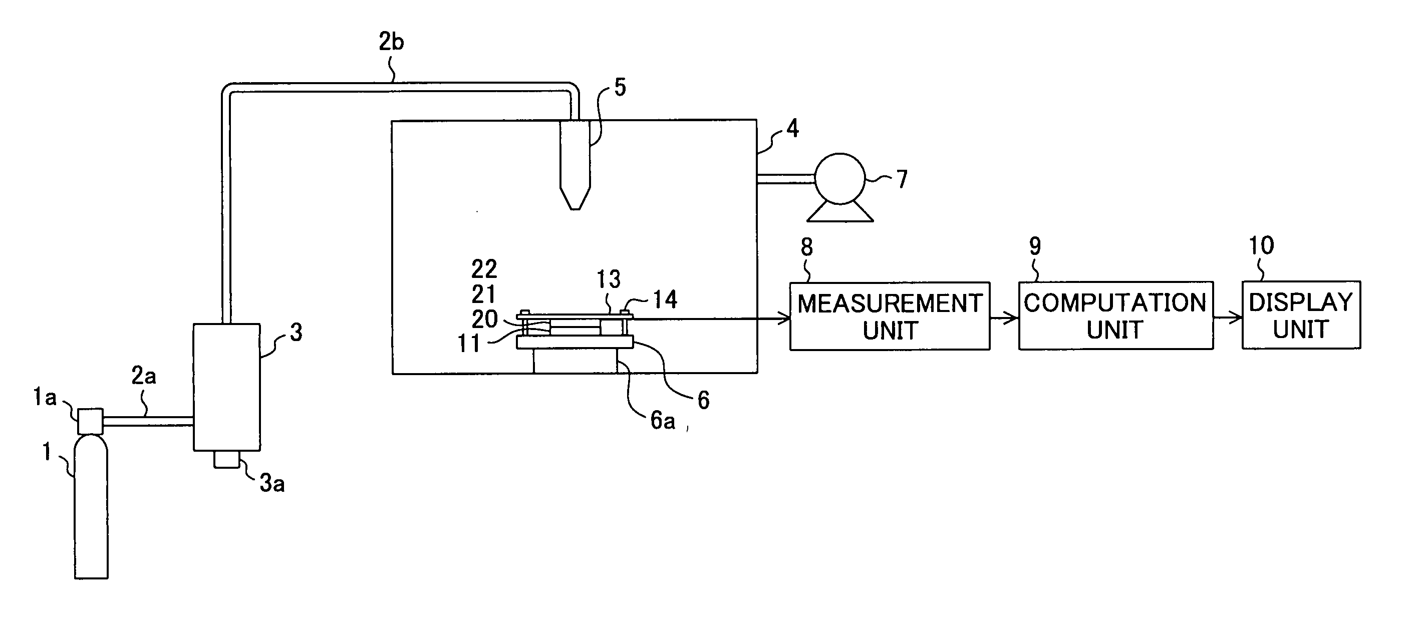
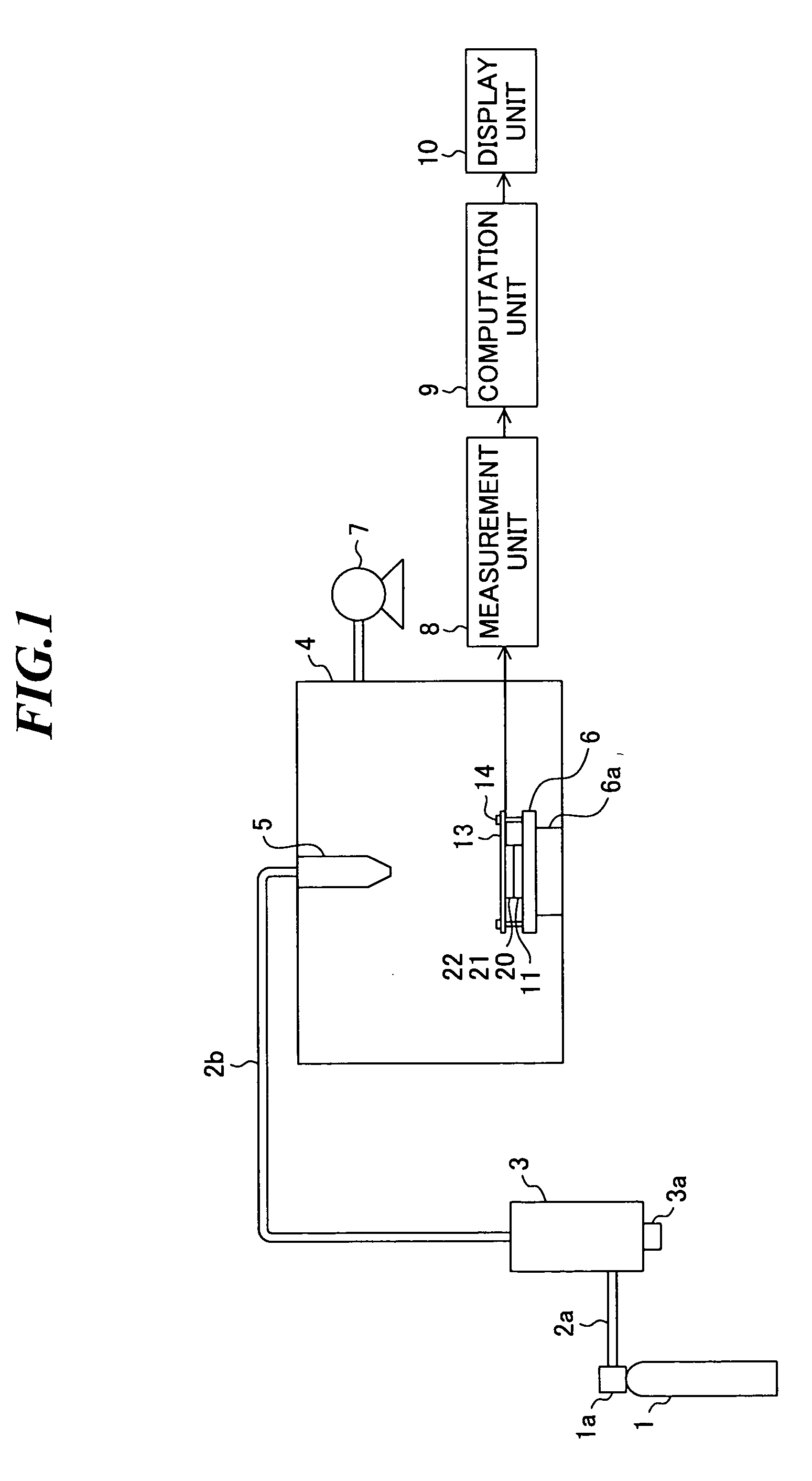
[0027]FIG. 1 is a schematic diagram showing a film formation apparatus according to the present invention. The film formation apparatus includes a compressed gas cylinder 1, carrier pipes 2a and 2b, an aerosol generation part including an aerosol generation chamber 3, a film formation chamber 4 in which film formation is performed, a nozzle 5 and a substrate holder 6 provided in the film formation chamber 4, an exhaust pump 7, a measurement unit 8, a computation unit 9 and a display unit 10.

[0028] The compressed gas cylinder 1 is filled with oxygen (O2) to be used as a carrier gas. Further, in the compressed gas cylinder 1, a pressure regulation part 1a for regulating the supplied amount of the carrier gas is provided. As the carrier gas, nitrogen (N2), helium (He), argon (Ar) dry air, or the like may be used other than that.

[0029] The aerosol generation chamber 3 is a container in which a micro powder of a raw material as a film formation material is disposed. An aerosol is genera...

second embodiment

[0061] Next, a film formation apparatus according to the present invention will be described. FIG. 11 is a schematic diagram showing the film formation apparatus according to the embodiment.

[0062] The film formation apparatus shown in FIG. 11 has a control unit 15 in place of the display unit 10 shown in FIG. 1. Other constitution is the same as the film formation apparatus shown in FIG. 1.

[0063] The control unit 15 controls the operation of the respective parts of the film formation apparatus so that a structure having present film thickness and film quality may be obtained based on the deposition rate, Vickers hardness, film thickness, etc. obtained by the computation unit 9 by utilizing the electric potential of the film formation surface measured by the measurement unit 8. That is, the control unit 15 controls the pressure regulation part 1a to change the flow rate of the carrier gas, controls the container driving part 3a to adjust the aerosol concentration, and / or controls th...


PUM

PropertyMeasurementUnit
Thicknessaaaaaaaaaa
Flow rateaaaaaaaaaa
Densityaaaaaaaaaa

Abstract

A film formation apparatus by which a film thickness can be precisely measured and whether the film quality is good or bad can be confirmed in a process of performing film formation according to the aerosol deposition method. The film formation apparatus includes: an aerosol generating unit for generating an aerosol by dispersing a raw material powder by a gas; a holding unit for holding a substrate on which a structure is to be formed; a nozzle for injecting the aerosol generated by the aerosol generating unit toward the substrate; and a measurement unit for measuring an electric potential of a film formation surface on the substrate.

Description

BACKGROUND OF THE INVENTION [0001] 1. Field of the Invention [0002] The present invention relates to a film formation apparatus for forming a structure on a substrate by spraying a law material powder at a high speed and deposit the powder thereon. [0003] 2. Description of a Related Art [0004] Recent years, in the field of micro electrical mechanical system (MEMS), fabrication of sensors, actuators, or the like employing piezoelectric ceramic by film formation has been studied in order to further integrate those elements for practical use. As one of the film formation methods, the aerosol deposition (AD) method known as a technology for forming a film of ceramic, metal, etc. receives attention. The AD method is a film formation method of generating an aerosol containing a raw material powder and injecting it toward a substrate from a nozzle and depositing the raw material on the substrate. Here, the aerosol refers to solid or liquid fine particles floating in a gas. [0005] In the AD...

Claims


Application Information

Patent Timeline
IPC IPC(8): B05C11/00C23C16/00B05C5/00
CPCC23C24/04
Inventor SASAKI, TSUTOMU
Owner FUJIFILM CORP
Why Eureka
Try Eureka