Covering material for solar thermal power generating system and solar thermal power generating system formed by spreading the covering material
a technology of solar thermal power generation system and covering material, which is applied in the direction of solar radiation prevention, wind motors, machines/engines, etc., can solve the problems of large area, large cost of such a replacement work of the roof of the heat collector, and significant decrease in power generation quantity. , to achieve the effect of excellent transparency, excellent power generation efficiency and high tensile yield strength
- Summary
- Abstract
- Description
- Claims
- Application Information
AI Technical Summary
Benefits of technology
Problems solved by technology
Method used
Image

Examples
example 1
Example of Preparing a Film
[0081] ETFE was prepared by a solution polymerization method described in JP-A-6-157616. The copolymerization composition of the ETFE, was that monomer units based on tetrafluoroethylene / monomer units based on ethylene / monomer units based on CH2═CHC4F9=52.4 / 46.4 / 1.2 (molar ratio). The ETFE was molded by using a melt extruder with a T-shaped die, at a die-temperature of 300° C. to produce a film of 100 μm in thickness. The tensile yield strength, the solar radiation transmittance and the weather resistance of the ETFE film obtained, were measured. The results are shown in Table 1.
example 2
Example of Preparing a Wide Film
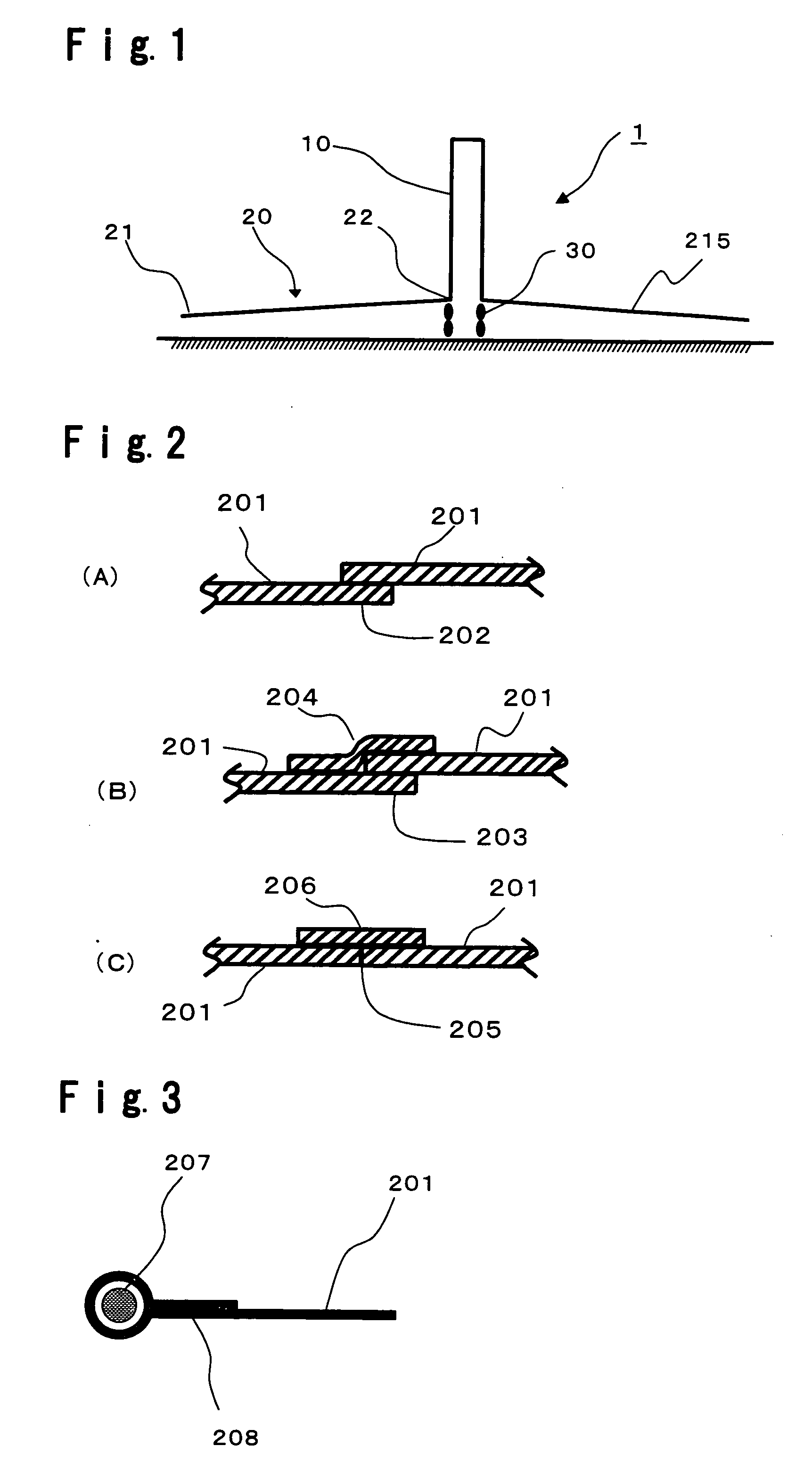
[0083] Two ETFE films having a width of 130 cm obtained by Example 1, were fusion bonded at a fusion-bonding temperature of 260° C. by using a thermal fusion bonder (manufactured by Queen Light Electronic Industries Ltd., Heat Sealer LHP-W705). This step was repeated to produce a large-width film having a width of 5 m. An ETFE film A was obtained by simply overlapping and fusion bonding portions within 3 cm from the ends of films (fusion-bonded portion of FIG. 2(A)). An ETFE film B was obtained by overlapping portions within 1 cm from the ends of films, and further overlapping a reinforcement film of 3.5 cm wide on the overlapping portion (the fusion-bonded portion of FIG. 2 (B)). An ETFE film C was obtained by butting the ends of films, overlapping a reinforcement film of 3.5 cm wide on the batted portion so as to bridge the butted portion, and fusion bonding the portion (fusion-bonded portion of FIG. 2(C)). Cross sections of the fusion-bonded porti...
example 3
Construction of a Solar Thermal Power Generation System
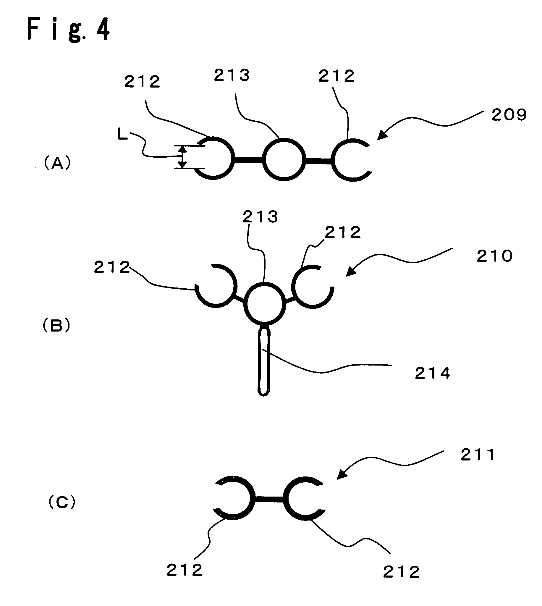
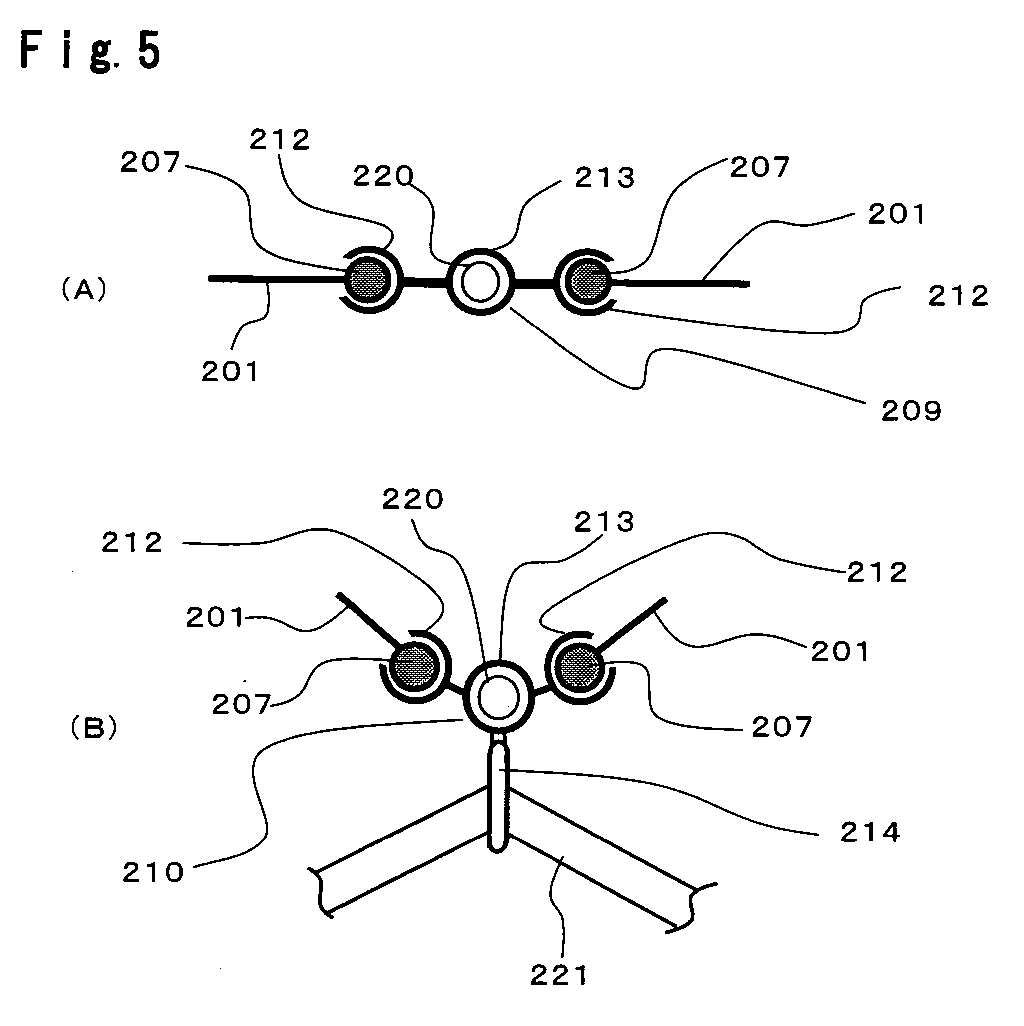
[0084] A cable (PVA cable) made of polyvinyl alcohol resin having a diameter of 1 cm was attached to the end of a ETFE film. Specifically, the peripheral portion of the ETFE film was folded so as to wrap the PVA cable to accommodate the PVA cable. Surfaces of the peripheral portion of the ETFE film folded in a loop shape were fusion-bonded to fix the PVA cable to the end of the film, to prepare a ETFE film having a PVA cable attached to its end. The cross section of the end of the ETFE film having a PVA cable attached to its end, is shown in FIG. 3. Then, using a connecting jigs, the ETFE film having a PVA cable attached to its end, was inserted into a connecting jig 209 and a connecting jig 210. The connecting jig 209 is fixed to a support-structural member, and the ETFE film covers the support-structural member and poles. A tension wire is let through a ring for letting tension wire, of the connecting jig 210. By pulling the ...
PUM
| Property | Measurement | Unit |
|---|---|---|
| Time | aaaaa | aaaaa |
| Tensile yield strength | aaaaa | aaaaa |
| Transmittivity | aaaaa | aaaaa |
Abstract
Description
Claims
Application Information
 - R&D
- Intellectual Property
- Life Sciences
- Materials
- Tech Scout
- Unparalleled Data Quality
- Higher Quality Content
- 60% Fewer Hallucinations
Browse by: Latest US Patents, China's latest patents, Technical Efficacy Thesaurus, Application Domain, Technology Topic, Popular Technical Reports.
© 2025 PatSnap. All rights reserved.Legal|Privacy policy|Modern Slavery Act Transparency Statement|Sitemap|About US| Contact US: help@patsnap.com