Solid-state laser device

a laser device and solid-state technology, applied in the field of solid-state laser devices, can solve the problems of large system size, complicated device mechanism, and need for more complicated structure, and achieve the effects of high accuracy, simple mechanism production, and high accuracy

Inactive Publication Date: 2006-06-15
KK TOPCON
View PDF3 Cites 22 Cited by
  • Summary
  • Abstract
  • Description
  • Claims
  • Application Information

AI Technical Summary

Benefits of technology

[0023] Also, according to the present invention, in the solid-state laser device described above, said output mirror switching means selectively positions said individual output mirrors provided on a rotating disk by rotating said rotating disk. Because positioning is performed by a rotating mechanism, high accuracy is assured, and the mechanism can be produced in simple design.
[0024] Further, according to the present invention, in the solid-state laser device described above, said output mirror switching means selectively positions said optical crystals for wavelength conversion and said individual output mirrors provided on a rotating disk by rotating said rotating disk. Because positioning is performed by a rotating mechanism, high accuracy is assured, and the mechanism can be produced in simple design.
[0025] Also, according to the present invention, in the solid-state laser device descri

Problems solved by technology

Thus, a number of components are required and the mechanism of the device is very complicated.
This means that more complicated stru

Method used


Image

  • Solid-state laser device
  • Solid-state laser device
  • Solid-state laser device

Examples


first embodiment

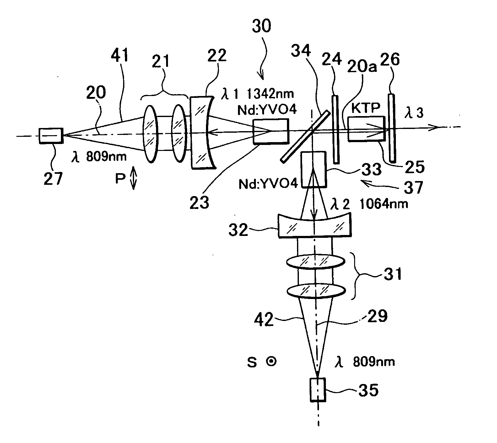
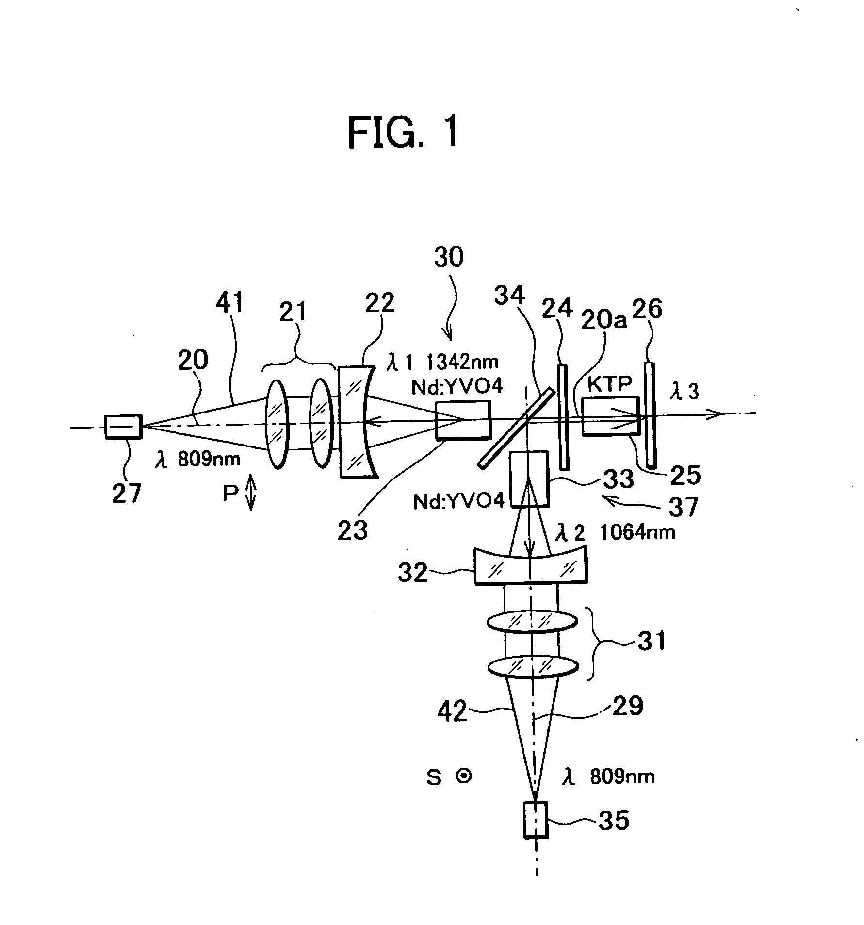
[0065] Next, description will be given on the invention having the basic optical system as given above by referring to FIG. 2 to FIG. 5.

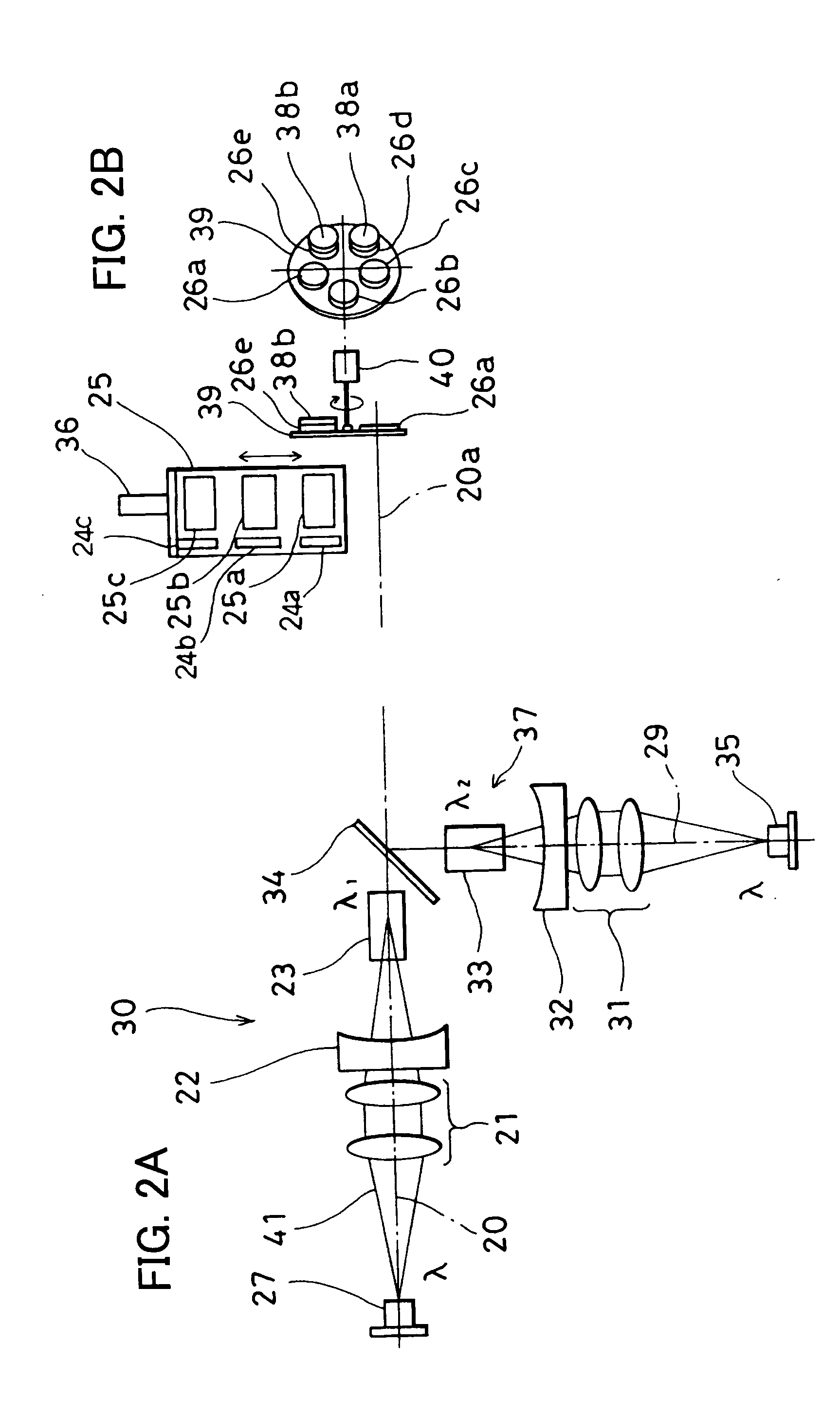
[0066]FIG. 2 shows basic arrangement of the first embodiment. In FIG. 2, the same component as shown in FIG. 1 is referred by the same symbol, and detailed description is not given here.

[0067] The wavelength conversion unit 25 is supported by a wavelength converting means 36. The wavelength converting means 36 can move the wavelength conversion unit 25 in a direction perpendicular to the commonly used optical axis portion 20a. Optical crystals 25a, 25b and 25c for wavelength conversion can be individually positioned on the commonly used optical axis portion 20a. When the optical crystal 25a for wavelength conversion is positioned on the commonly used optical axis portion 20a while the first fundamental wave and the second fundamental wave are oscillated, the sum frequency SFM is oscillated. When the optical crystal 25b for wavelength conversion is ...

second embodiment

[0088] Referring to FIG. 6 and FIG. 7, description will be given below on the invention.

[0089] In FIG. 6 and FIG. 7, the same component as shown in FIG. 2 to FIG. 5 is referred by the same symbol, and detailed description is not given here.

[0090] In the second embodiment, the output mirror 26 and the intermediate mirror 24 are incorporated in the wavelength conversion unit 25. It is designed in such manner that the optical crystal of the wavelength conversion unit 25 is switched over by the wavelength switching means 36, and that the output mirror 26 and the intermediate mirror 24 are switched over integrally with the optical crystals for wavelength conversion.

[0091] The wavelength conversion unit 25 comprises optical crystals 25a, 25b and 25c for wavelength conversion and also comprises individual output mirrors 26a, 26b, 26c, 26d and 26e to match the types of the projected laser beams. There are provided individual output mirrors 26a, 26b and 26c on exit sides of the laser beams...

third embodiment

[0104]FIG. 8 shows the invention. In FIG. 8, the same component as shown in FIG. 7 is referred by the same symbol, and detailed description is not given here.

[0105] In the third embodiment, the Q-SW element 38 is incorporated in the basic optical system. The Q-SW element 38 is provided between the intermediate mirror 24 and the polarization beam splitter 34 on the commonly used optical axis portion 20a.

[0106] When the optical crystal 25a for wavelength conversion is positioned on the commonly used optical axis portion 20a and the LD light emitters 27 and 35 are turned on at the same time, a pulsed laser beam of SFM is projected. When the optical crystal 25b for wavelength conversion is positioned on the commonly used optical axis portion 20a, and only the LD light emitter 27 is turned on, a pulsed laser beam converted to SHG1 is projected. When the optical crystal 25c for wavelength conversion is positioned on the commonly used optical axis portion 20a and only the LD light emitter...


PUM


Abstract

A solid-state laser device, comprising a first optical axis and a second optical axis having a commonly used optical axis portion and separated by an optical axis separating means, a first resonator composed on the first optical axis, a second resonator composed on the second optical axis, a first light emitter for allowing an excitation light to enter the first resonator, a second light emitter for allowing an excitation light to enter the second resonator, a wavelength conversion unit provided on the commonly used optical axis portion, and an output mirror provided on an exit side of the wavelength conversion unit, wherein the wavelength conversion unit comprises two or more optical crystals for wavelength conversion, the output mirror has two or more individual output mirrors, and a wavelength of a laser beam to be projected is determined by selection of turning-on or turning-off of the first light emitter and the second light emitter, and also by selection of the optical crystals for wavelength conversion and the individual output mirrors depending on turning-on and turning-off of the first light emitter and the second light emitter.

Description

BACKGROUND OF THE INVENTION [0001] The present invention relates to a solid-state laser device, by which laser beams with a plurality of wavelengths can be projected. [0002] In recent years, laser beams have been widely used in fields of medical treatment. For example, a laser operation system for medical treatment is known, by which laser beams are projected to an affected site or sites of a patient. [0003] Medical instruments and systems using laser beams are used for the purposes such as photocoagulation, resection, incision, etc. of the site or sites to be treated on non-contact basis. Color, i.e. wavelength, of a laser beam used differs according to the type of medical treatment. In a laser device used as a laser light source of the medical instrument or system, it is desirable to supply laser beams with a plurality of wavelengths to the medical instrument or system. [0004] As a laser light source, it is now wanted to replace the conventional type Kr laser or dye laser to a dio...

Claims


Application Information

Patent Timeline
IPC IPC(8): H01S3/10
CPCH01S3/07H01S3/08086H01S3/082H01S3/09415H01S3/105H01S3/109H01S3/11H01S3/1611H01S3/1673A61B18/20H01S3/1123H01S3/1061
Inventor ENO, TAIZOMOMIUCHI, MASAYUKIGOTO, YOSHIAKI
Owner KK TOPCON
Why Eureka
Try Eureka