Apparatus for nondestructive measurement of fissle materials in solid radioactive wastes

a technology of solid radioactive waste and detector, which is applied in the direction of instruments, nuclear elements, greenhouse gas reduction, etc., can solve the problems of insufficient precision in fissile nuclides determination, not as effectively admitted into the core areas, etc., and achieve the effect of reducing or eliminating unwanted counts, facilitating selective isolation of target counts, and increasing the probability of target counts

Inactive Publication Date: 2006-06-15
JAPAN ATOM ENERGY RES INST
View PDF9 Cites 6 Cited by
  • Summary
  • Abstract
  • Description
  • Claims
  • Application Information

AI Technical Summary

Benefits of technology

[0015] The present invention is an improvement of the technology described in JP 11-64528 A for analyzing the data of measurement obtained by the active neutron method; in JP 11-64528 A, the fast neutrons emitted from the neutron generating tube are scattered in a radioactive solid waste under analysis and slowed to thermal neutrons which are allowed to bombard the nuclei of the fissile material in said solid waste, thereby causing its fission and the count of the released fission neutrons is selectively isolated and integrated over time to give a total count, which is used as a measure of the total quantity of the fissile material contained in the solid waste under analysis. Specifically, the invention provides an apparatus capable of acquiring data of measurement such that the probability of incidence of the target counts is sufficiently increased to reduce or eliminate unwanted counts, thereby facilitating selective isolation of the target counts.
[0018] As the material with which the measurement system in the detection apparatus used in the method described in JP 11-64528 A is built, the neutron absorber-loaded polyethylene which considerably slows down and absorbs fast neutrons is replaced by iron or an alloy thereof which have no moderating action but have great ability to reflect fast neutrons. With this design, the neutrons admitted into the solid waste under analysis are not only the fast neutrons that go direct into the solid waste from the neutron generating tubes but also the high-energy neutrons reflected from the measurement system. As a result, the probability of incidence of nuclear fissions in the method of JP 11-64528 A is sufficiently increased to enhance the sensitivity of measurement.
[0026] In the apparatus for nondestructive measurement that is used in the method described in JP 11-64528 A, the position-dependent difference in detection sensitivity is further reduced by providing the solid radioactive waste under analysis in the measurement system such that it is placed between the set of neutron detectors and that of neutron generating tubes. To be more specific, the neutron detectors are provided behind the solid radioactive waste under analysis on the side that is remote from the neutron generating tubes.
[0028] In order to reduce the leakage of neutrons, polyethylene loaded with a thermal neutron absorber is provided outside the fast neutron reflector such as iron in the measurement system.

Problems solved by technology

The neutrons admitted into the solid radioactive waste to be analyzed by the active neutron method are those of low energy which have been slowed down by the surrounding graphite moderator system, so they are effectively admitted into the areas near the surface of the solid radioactive waste but not as effectively admitted into the core areas near its center.
Hence, the detection sensitivity for fissile nuclides present in the core areas near the center of the solid radioactive waste is more than a hundred times less than that for fissile nuclides present in the areas near the surface and the precision in determination of fissile nuclides is not satisfactory if they are distributed unevenly within the solid radioactive waste.

Method used


Image

  • Apparatus for nondestructive measurement of fissle materials in solid radioactive wastes
  • Apparatus for nondestructive measurement of fissle materials in solid radioactive wastes
  • Apparatus for nondestructive measurement of fissle materials in solid radioactive wastes

Examples


example 1

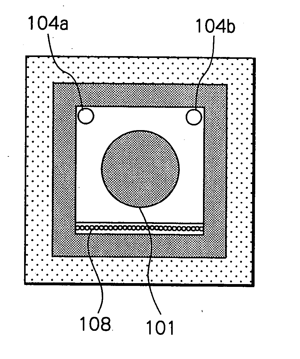
[0071]FIG. 20 shows a model for simulation by the Monte Carlo method that is intended to implement the first and fourth means of solving the problems of the prior art, thereby demonstrating their effectiveness. The wall surrounding the space of measurement in a model for the system of measurement by the active neutron method was built with iron (Fe) and a solid radioactive waste to be analyzed was placed in the space defined by two neutron generating tubes and 28 He-3 detectors.

[0072] In the simulation by the Monte Carlo method, as in the experiment of measurement described in JP 11-64528 A, a plutonium radiation source 1201 simulating the fissile material in the solid radioactive waste to be analyzed was placed in the concrete-filled drum 202 and moved through a hole from the center 1203 outward to the surface at 2.5-cm intervals. At the individual positions of the movement, about 20,000,000 fast neutrons having an energy of 14 MeV were emitted from neutron generating tubes 104a a...

example 2

[0078] In the second means of solving the problems, the fast neutron reflector surrounding the solid radioactive waste under analysis in the apparatus as the first means of solving the problems which intends to perform nondestructive measurement of fissile materials in the solid waste is built with lead or an alloy thereof.

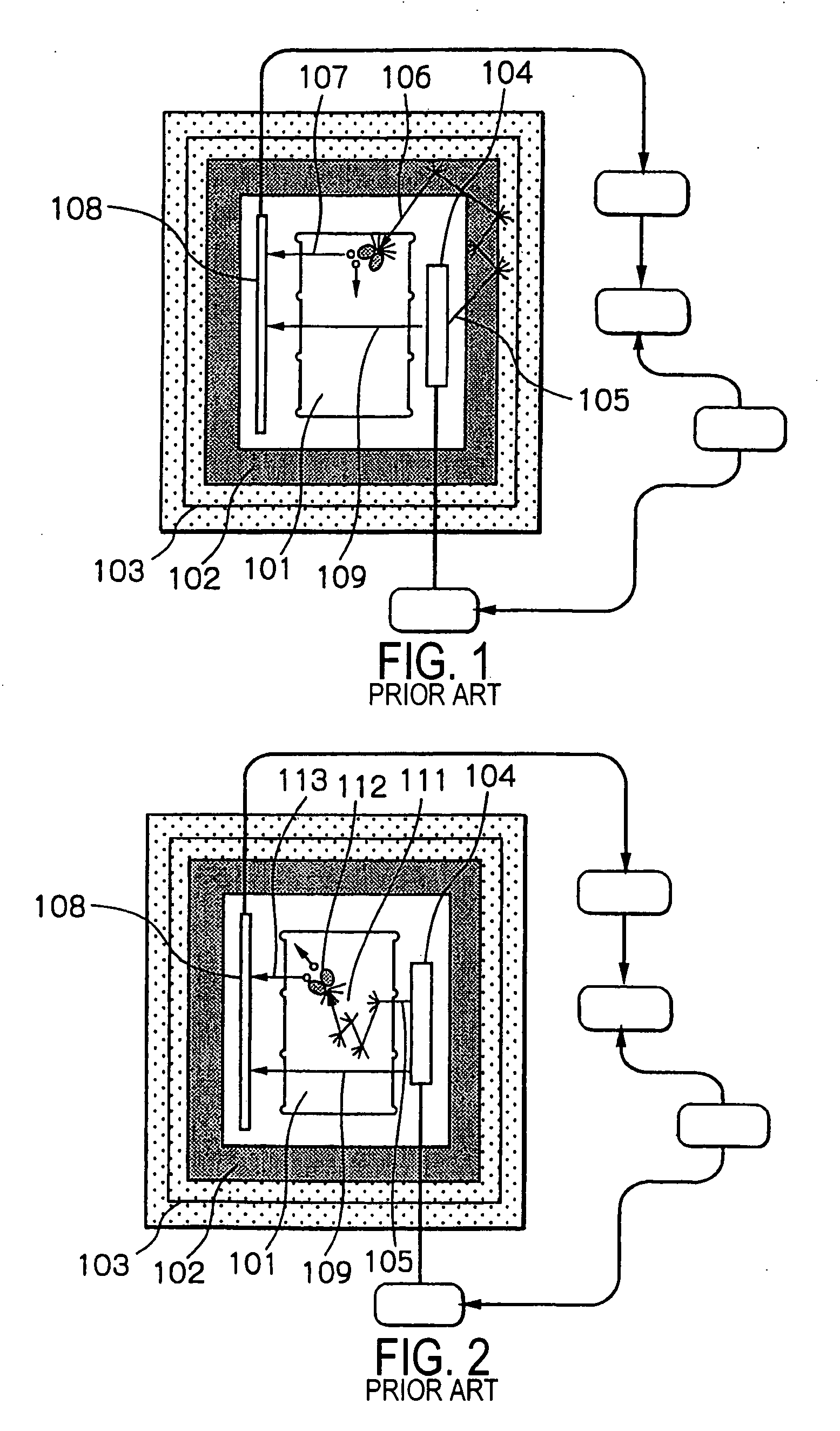
[0079]FIG. 23 shows a specific example of this second means of solving the problems by using lead. The system is identical to the detector shown in FIG. 1 which performs measurement by the active neutron method, except that the neutron moderator 102 which is either graphite, polyethylene or boron-doped polyethylene is eliminated from the neutron moderating reflector unit and that the drum 101 containing the solid radioactive waste under analysis, the neutron generating tubes 104a and 104b, and the He-3 detectors 108a and 108b are enclosed solely with a reflector 1102 made of lead or its alloy. Given very small ability of the lead alloy to slow down fast neutrons,...

example 3

[0080] In the third means of solving the problems, the fast neutron reflector surrounding the solid radioactive waste under analysis in the apparatus as the first means of solving the problems which intends to perform nondestructive measurement of fissile materials in the solid waste is built with a zirconium alloy.

[0081]FIG. 24 shows a specific example of this third means of solving the problems by using zirconium. The drum 101 containing the solid radioactive waste under analysis, the neutron generating tubes 104a and 104b, and the He-3 detectors 108a and 108b are enclosed solely with a reflector 1103 made of zirconium or its alloy. Zirconium or its alloys are as good reflectors of fast neutrons as iron and lead but their ability to slow down fast neutrons is very small; hence, the proportion of the unwanted neutron count due to the thermal neutrons that are admitted from the outside into the solid radioactive waste to cause nuclear fission is drastically reduced. As a result, th...


PUM


Abstract

As the material with which a measurement system in a detection apparatus is built, the neutron absorber-loaded polyethylene which considerably slows down and absorbs fast neutrons is replaced by iron or an alloy thereof which have no moderating action but have great ability to reflect fast neutrons. With this design, the neutrons admitted into the solid waste under analysis are not only the fast neutrons that go direct into the solid waste from the neutron generating tubes but also the high-energy neutrons reflected from the measurement system. The probability of incidence of nuclear fissions is sufficiently increased to enhance the sensitivity of measurement.

Description

[0001] This application is a continuation of application Ser. No. 10 / 125,492, filed Apr. 19, 2002, which is based upon and claims the benefit of priority from Japanese Patent Application No. 209272 / 2001, filed Jul. 10, 2001 and Japanese Patent Application No. 380313 / 2001 filed Dec. 13, 2001, the entire contents of this application are incorporated herein by reference.BACKGROUND OF THE INVENTION [0002] This invention relates to the technology of measuring the contents of plutonium and other fissile materials in solid radioactive wastes by a nondestructive approach before disposal. When fast neutrons are scattered in the solid radioactive waste and slowed down to thermal neutrons, they will cause fission of nearby fissile materials to generate fission neutrons. The Applicant previously proposed a method and an apparatus for selective measurement of such fission neutrons (JP 11-64528 A). The present invention particularly relates to a system for achieving a further improvement in sensi...

Claims


Application Information

Patent Timeline
Patent Type & Authority Applications(United States)
IPC IPC(8): G21G1/06G21F1/08G01T1/167G21C17/06G21F1/10G21F3/00G21F9/36
CPCG21C17/063Y02E30/30
Inventor HARUYAMA, MITSUO
Owner JAPAN ATOM ENERGY RES INST
Why Eureka
Try Eureka