
Prevention of cavitation corrosion

a technology of cavitation corrosion and corrosion prevention, which is applied in the direction of rotary propellers, marine propulsion, vessels, etc., can solve the problems of large noise, high energy consumption, and major damage, and achieve the effect of reducing noise, reducing energy consumption, and reducing energy consumption

Inactive Publication Date: 2006-06-15
WRIGLEY DAVID
View PDF10 Cites 2 Cited by
  • Summary
  • Abstract
  • Description
  • Claims
  • Application Information

AI Technical Summary

Benefits of technology

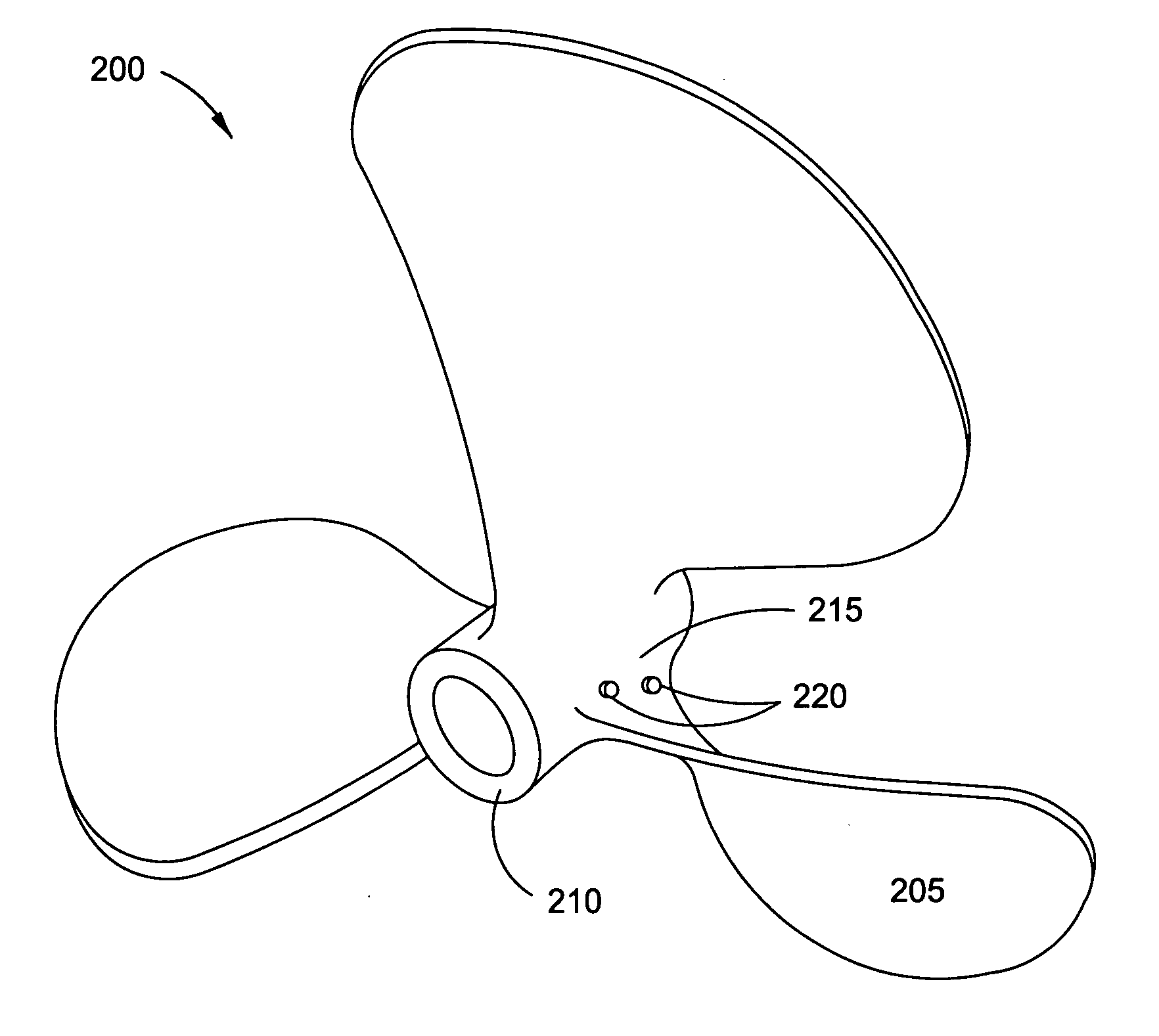
[0008] By modifying the hub, whether by casting a new propeller with a redesigned hub, or by retrofitting an existing hub, applicant has discovered that the elimination of corrosion occurs when a high Developed Area Ratio (DAR) propeller hub has one or more raised protrusions on the surfaces of the propeller hub between each blade seat. The addition of the raised protrusions discourages the formation of low pressure areas around the hub. By removing the low pressure areas from the immediate area around the hub, the shock waves caused by the collapse of the low pressure areas is moved away from the propeller, thus eliminating corrosion impact damage.

Problems solved by technology

When the vacuums of cavitation collapse, they create large amounts of noise.
The collapse also produces very high energy and can cause major damage.
A solid body can become pitted and worn away due to the repeated collapse of these vacuums.
Cavitation corrosion occurs frequently on propellers, such as those used by aircraft and marine vessels.
When the vacuums collapse, they typically cause strong shockwaves in the fluid, which can cause damage to the blades or the propeller's hub.
This is particularly troublesome in high speed propellers, as the damage to the propeller reduces overall efficiency.
However, this approach does not completely solve the problem as the partial vacuums still can form around the hub and cause pitting and damage to the hub.

Method used


Image

  • Prevention of cavitation corrosion
  • Prevention of cavitation corrosion
  • Prevention of cavitation corrosion

Examples


Embodiment Construction

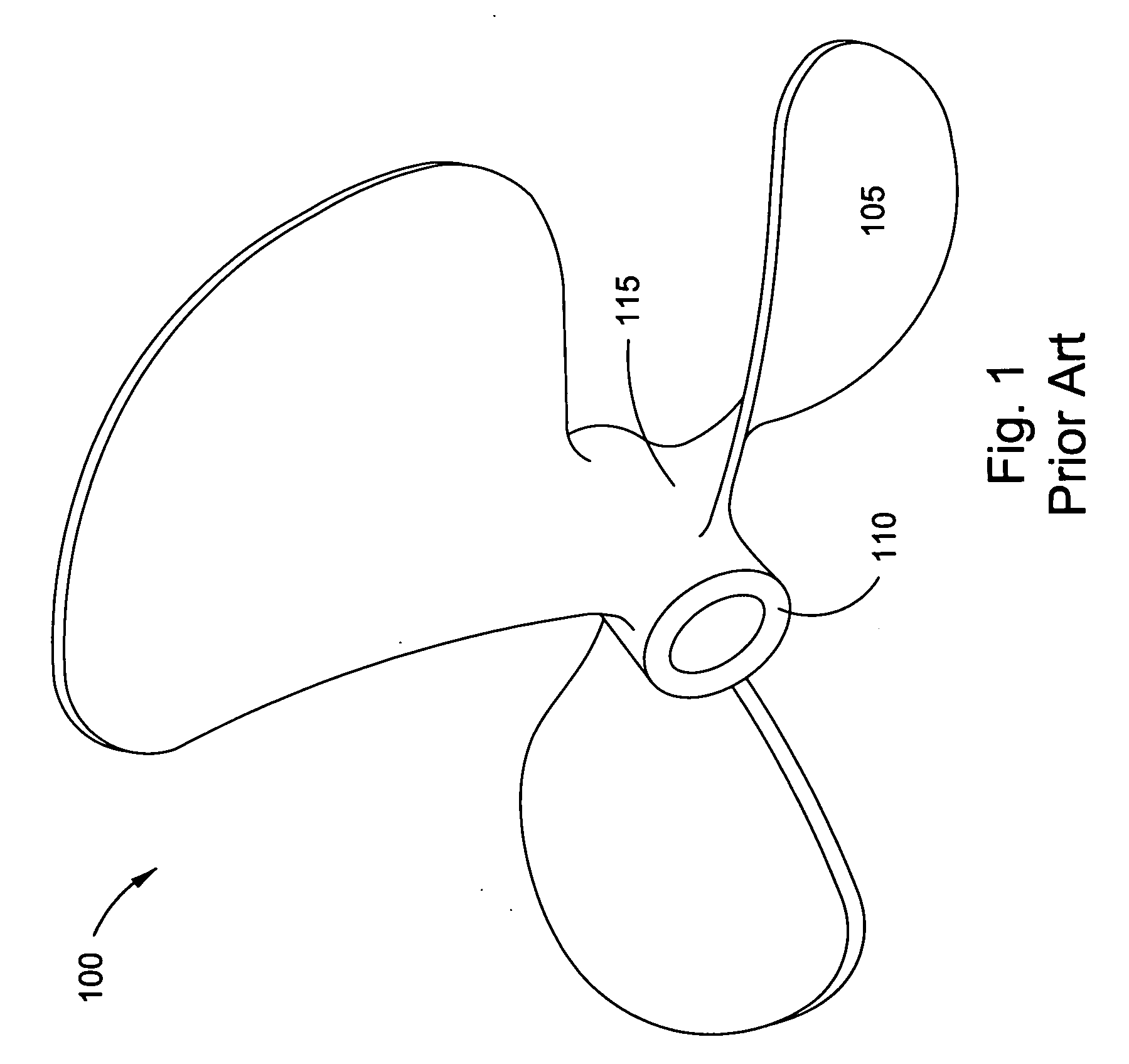
[0014]FIG. 1 illustrates a three blade right hand rotation propeller 100. Blade 105 is in the area of blade root 115. In the normal operation of a high speed propeller, low pressure areas, or partial vacuums, develop around hub 110. As the partial vacuums collapse, shock waves are sent out from the center of the collapsed vacuum. These shock waves reflect off of hub 110 and can cause cavitation corrosion, particularly in the area of blade root 115.

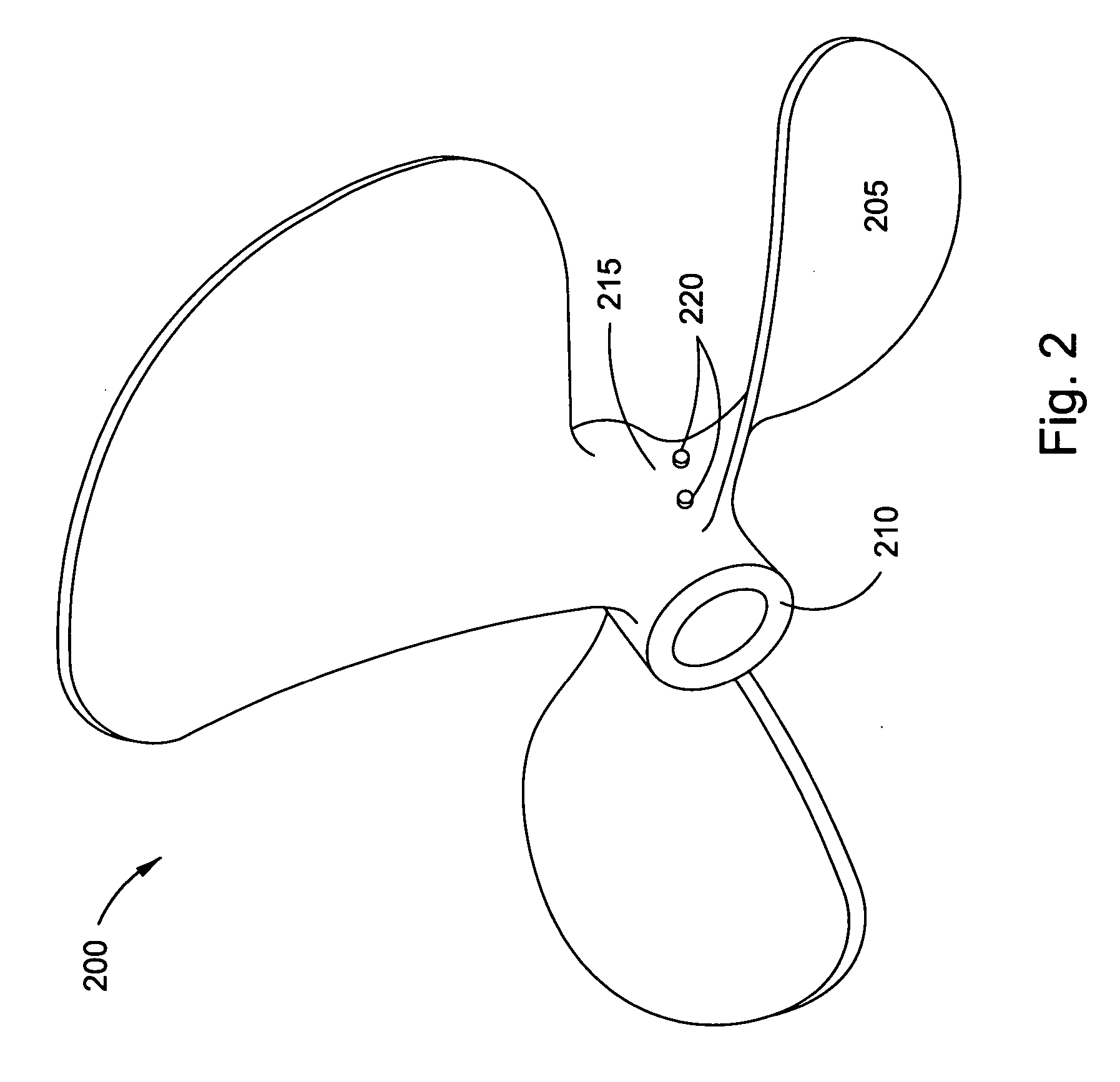
[0015]FIG. 2 illustrates a similar propeller to that of FIG. 1, a three blade right hand rotation propeller 200. However, in FIG. 2, the propeller is fitted with an embodiment of the present invention including a disruption means. Raised nubs 220 are integrated into blade root 215. The term integrated is hereby defined as to form, coordinate, or blend into a functioning or unified whole, meaning the disruption means may be cast along with the propeller to form a unified body, or the disruption means may be individual pieces brought togeth...


PUM


Abstract

The present invention directly deals with the problem of cavitation corrosion by modifying the hub of a propeller to eliminate low pressure areas. The present invention is the placement, formation, and / or insertion, on a propeller, of a non-smooth area in each facet of the hub between each of the blades. This area is also sometimes referred to as the “blade root”. The exact configuration of the raised area can vary from a longitudinal raised area to single or multiple bumps or buttons to single or multiple pointed projections. By modifying the hub, whether by casting a new propeller with a redesigned hub, or by retrofitting an existing hub, the elimination of corrosion occurs when a high Developed Area Ratio (DAR) propeller hub has one or more raised protrusions on the surfaces of the propeller hub between each blade seat. The addition of the raised protrusions discourages the formation of low pressure areas around the hub. By removing the low pressure areas from the immediate area around the hub, the shock waves caused by the collapse of the low pressure areas is moved away from the propeller, thus eliminating corrosion impact damage.

Description

CROSS-REFERENCE TO RELATED PATENTS [0001] This application claims the benefit, under Title 35, United States Code, Sec. 119(e), of U.S. provisional Application No. 60 / 636,176 filed Dec. 14, 2004, titled PREVENTION OF CAVITATION CORROSION, the disclosure of which, including all appendices and all attached documents, is hereby incorporated by reference in its entirety.FIELD OF THE INVENTION [0002] The present invention relates generally to design of propulsion devices, more specifically to the design of high efficiency propellers. BACKGROUND OF THE INVENTION [0003] Cavitation is the formation of partial vacuums in a liquid by a swiftly moving solid body or by high intensity sound waves. These partial vacuums are caused by a low pressure in the liquid. When the local ambient pressure at a point in the liquid falls below the liquid's vapor pressure, the liquid undergoes a phase change to a gas, creating “bubbles” or, more accurately, partial vacuums in the liquid. [0004] When the vacuum...

Claims


Application Information

Patent Timeline
Patent Type & Authority Applications(United States)
IPC IPC(8): B63H16/20
CPCB63H1/18
Inventor WRIGLEY, DAVID
Owner WRIGLEY DAVID
Learn More