Boiling and cooling device

a cooling device and cooling tank technology, applied in the direction of basic electric elements, semiconductor devices, reinforcing means, etc., can solve the problems of inability to push the heat sink to the heating body with an appropriate force, easy deformation of the cooling tank, etc., to achieve enhanced heat transfer characteristics, low manufacturing cost, and simple structure

Inactive Publication Date: 2006-06-22
DENSO CORP
View PDF19 Cites 4 Cited by
  • Summary
  • Abstract
  • Description
  • Claims
  • Application Information

AI Technical Summary

Benefits of technology

[0024] As nothing corresponding to the block provided in the fourth aspect of the present invention is needed, the structure can be made simple and the low manufacturing cost can be realized. Further, there is no heat resistance at the contact face of the block with

Problems solved by technology

However, the following problems may be encountered.
Accordingly, the container of the cooling tank is easily deformed w

Method used


Image

  • Boiling and cooling device
  • Boiling and cooling device
  • Boiling and cooling device

Examples


second embodiment

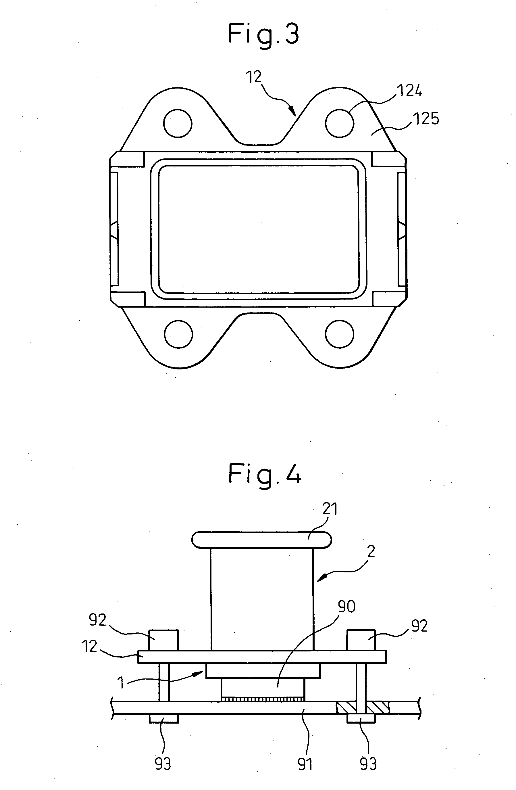
[0072] In this embodiment, it is unnecessary to provide the block 18 which is needed in the Therefore, the structure can be made simple and the manufacturing cost can be reduced. Further, as no heat resistance exists between the block 18 and the base plate 16, the heat transfer characteristic can be improved.

[0073] Finally, another embodiment will be explained below. In the embodiments described above, the reinforcing member 122 or the frame 17 is made of stainless steel. However, the reinforcing member 122 or the frame 17 may be made of the other iron material such as carbon steel.

third embodiment

[0074] In the second and the third embodiment, the base plate 16 and the frame 17 are integrated with each other into one body by means of brazing. However, the base plate 16 and the frame 17 may be integrated with each other by means of caulking.


PUM

PropertyMeasurementUnit
Stiffnessaaaaaaaaaa

Abstract

A container composes the refrigerant tank 1 including: a block 13 made of copper, one face of which is exposed inside the refrigerant tank 1, the other face of which is contacted with the heating body 90; and a lamination plate 12 composed of three layer structural material in which a reinforcing material 122 is interposed between skins 121 made of copper, the lamination plate 12 being joined to the block 13. Further, heat can be transferred between the refrigerant and the heating body 90 via a block 13 made of copper, the heat transfer characteristic of which is good. After the completion of the brazing process, the rigidity of the container composing the refrigerant tank can be ensured by a reinforcing member 122, the rigidity of which is higher than that of copper.

Description

BACKGROUND OF THE INVENTION [0001] 1. Field of the Invention [0002] The present invention relates to a boiling and cooling device for cooling a heating body of a semiconductor element by the transfer of latent heat generated when a refrigerant is boiled and condensed. [0003] 2. Description of the Related Art [0004] According to the boiling and cooling device disclosed in the official gazette of JP-A-2004-37074, a material and a method of manufacturing a container to compose a refrigerant tank are not described. However, when consideration is given to the heat conduction characteristics, it is assumed that the boiling and cooling device is formed out of copper by means of press forming, forging or cutting. A refrigerant tank and a radiating section are usually joined to each other by means of brazing. [0005] On the other hand, in the case where a heat sink is applied to a heating body, in order to reduce the contact heat resistance, it is usually required that the heat sink is attach...

Claims


Application Information

Patent Timeline
IPC IPC(8): F28D15/00
CPCF28D15/0266F28D15/0283F28D15/046H01L23/345H01L23/3672Y10T29/49353H01L2924/0002H01L23/427F28F2225/00H01L2924/00
Inventor OKAMOTO, YOSHIYUKITANAKA, HIROSHIISHII, SHO
Owner DENSO CORP
Why Eureka
Try Eureka