
Driving aid device

a technology of driving aid and driver's seat, which is applied in the direction of color television, television systems, instruments, etc., can solve the problems of unsatisfactory solutions and various solutions, and achieve the effects of reducing aggressiveness of adverse sources, increasing night vision, and greatly improving driving comfor

Inactive Publication Date: 2006-06-22
TIETRONIX OPTICS
View PDF3 Cites 10 Cited by
  • Summary
  • Abstract
  • Description
  • Claims
  • Application Information

AI Technical Summary

Benefits of technology

[0036] According to a particular embodiment, the device comprises a gyroscopic platform intended for the stability of the coronagraph and means of correcting any delays in the detection / feedback loop during rapid movements.
[0043] In the case of road safety, the vision of the driver is by far the essential driving instrument. The eye is the main detector from which the entire algorithm for navigation of the vehicle on the road is constructed. In a more and more aggressive environmental context, essentially due to road usage always close to saturation, the margin for error is considerably reduced, whilst the performance of the driver, in particular his vision, has remained a constant. The protection of this essential instrument is therefore obvious. The Eclipse technology makes it possible to participate in this protection, as well as the protection of the optical systems which are being produced to come to the assistance of the vision of the driver. In the particular case of night vision, as will be seen later, the Eclipse system is not only a protection means but also a means of increasing night vision.
[0045] The basic application is intended to protect any optical system against dazzling, ranging from the eye to cameras and other optical sensors.
[0051] In addition to this basic function (filtration), the invention allows the following supplementary functions, in the case of a use in terrestrial transportation: superimposition of various items of information of the HUD type, amplification of excessively weak light, maintenance of an optimum level of quality of landscape observed in the case of damage to the normal input interface between the user and this landscape (windscreen for example).
[0052] The invention is particularly useful for terrestrial transport (car, coach, bus, motorcycle etc), during the night-time period. The device then proceeds with a selective dynamic filtration of the dazzle from the car headlights or any other light situated in the opposite direction to the vehicle. At the same time as the attenuation of strong sources, it offers the possibility of amplifying the sources of low light so as to considerably increase night vision. The problem encountered by a night-time driver is similar to the problem encountered in space, where the light source (the sun) is an intense light source standing out from a black sky. In night-time driving, the theatre is an identical black surface where the headlights of opposing cars (and possibly other sources), and the thin zone illuminated by the car headlights, stand out. It is easy to imagine the conditions obtained in the Eclipse window: an illuminated theatre seen by the camera amplifying the low light, the strip of road illuminated by the headlights under the Eclipse window. The camera is itself protected by the means of occulting the intense sources which prevent its own blinding, the adverse lights are seen as light spots of low intensity. In addition to this advantage with regards to safety, driving comfort is greatly improved by the fact that the light window placed in front of the driver makes it possible to choose the average light intensity corresponding to the moment when the pupil of the eye is struggling to remain open because of the low light from the theatre, whilst it would close in order to reduce the aggressiveness of adverse sources. The tendency will therefore be to be situated at a start of closure of the pupil whilst keeping an excellent view of the essential area.

Problems solved by technology

The problem posed by such equipment is that of processing the content of high contrast, for example the appearance of a headlight in the field of view of the camera, as well as that of the aberrations resulting from the shift between the virtual image and the real image.
These various solutions are not totally satisfactory since they do not provide a virtual image visible to infinity under all visibility conditions: day, night, dazzling areas by a source highly contrasted with respect to ambient lighting.

Method used


Image

  • Driving aid device
  • Driving aid device
  • Driving aid device

Examples


Embodiment Construction

)

[0062] The invention is depicted hereinafter in the form of non-limiting examples.

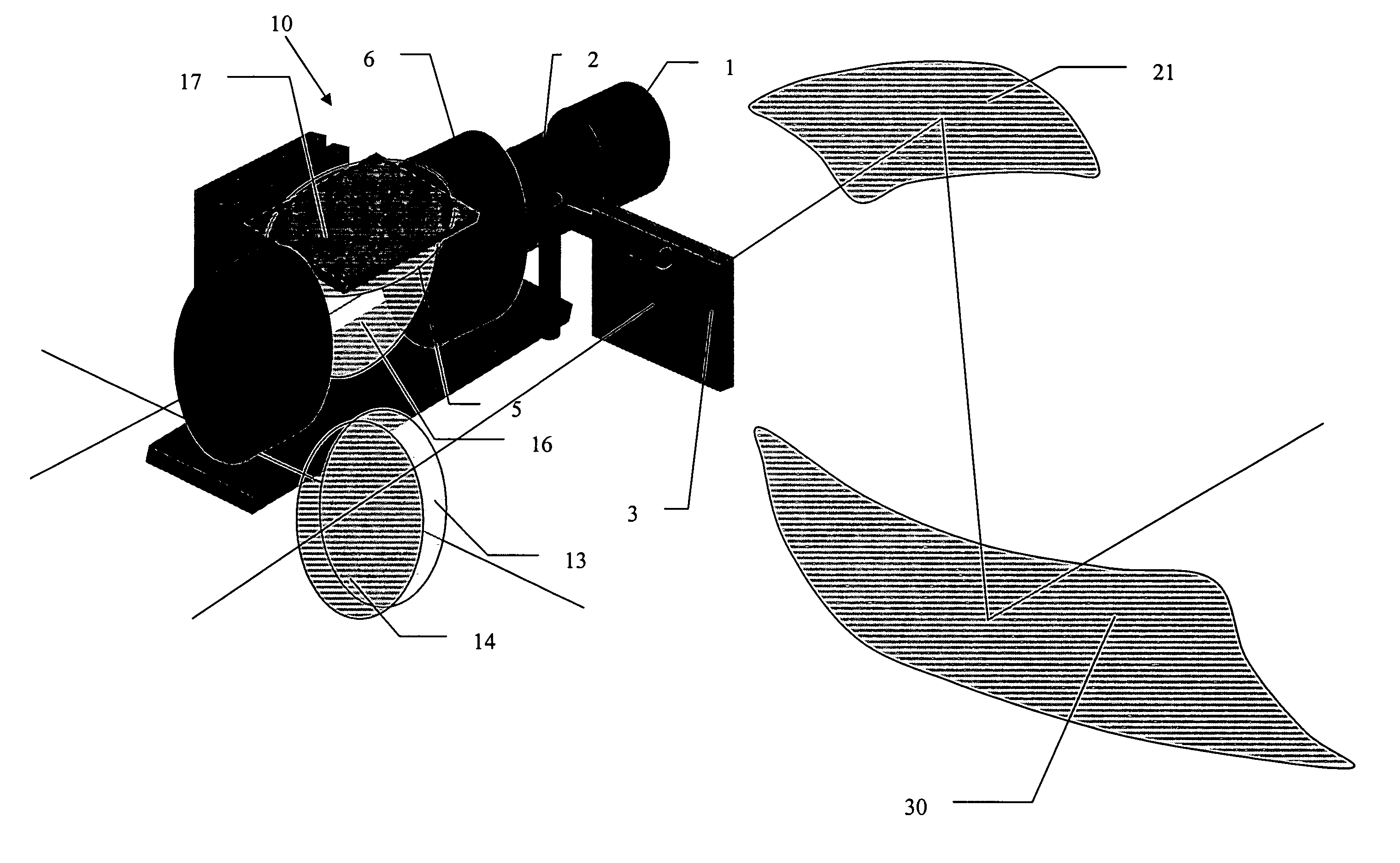
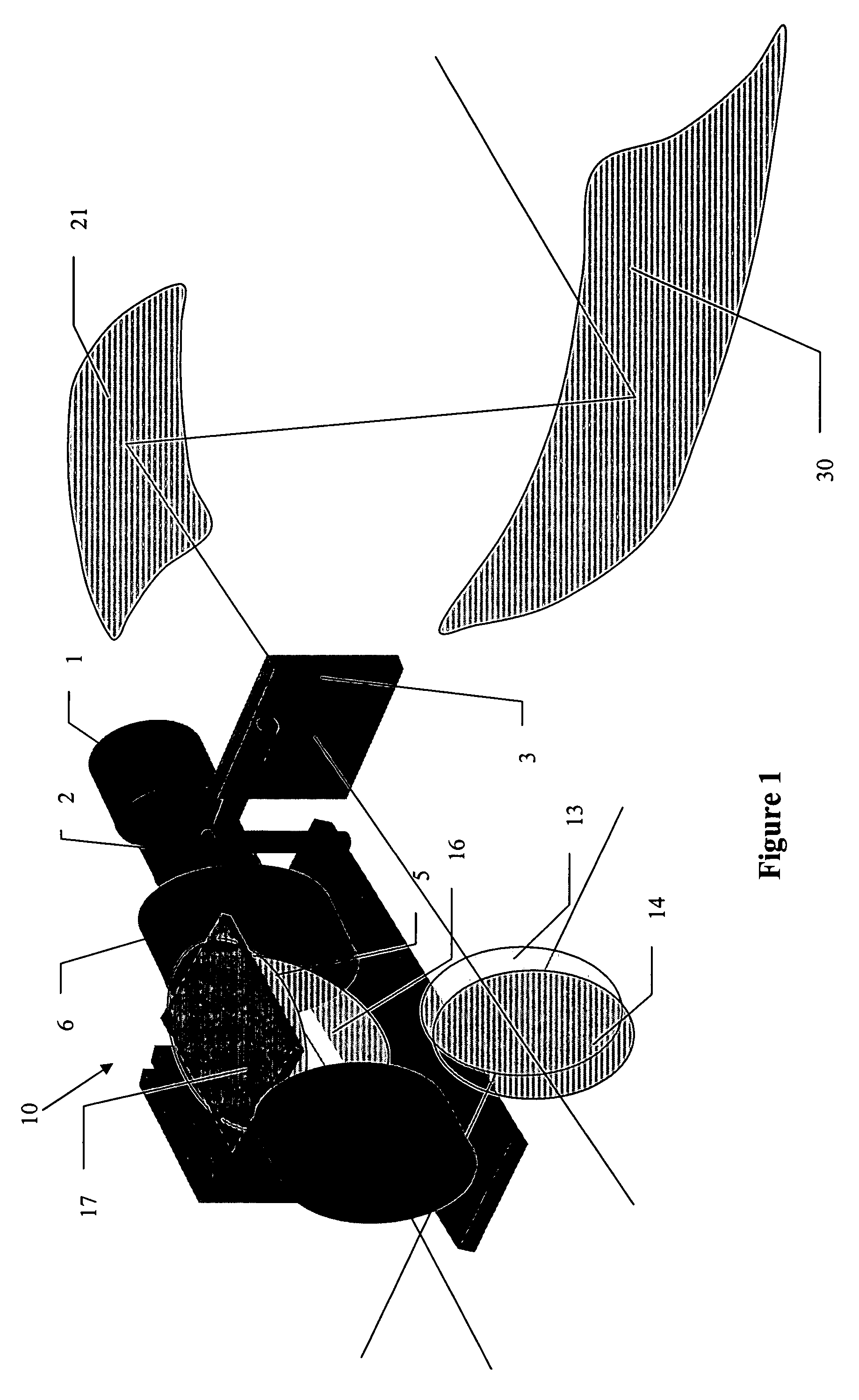
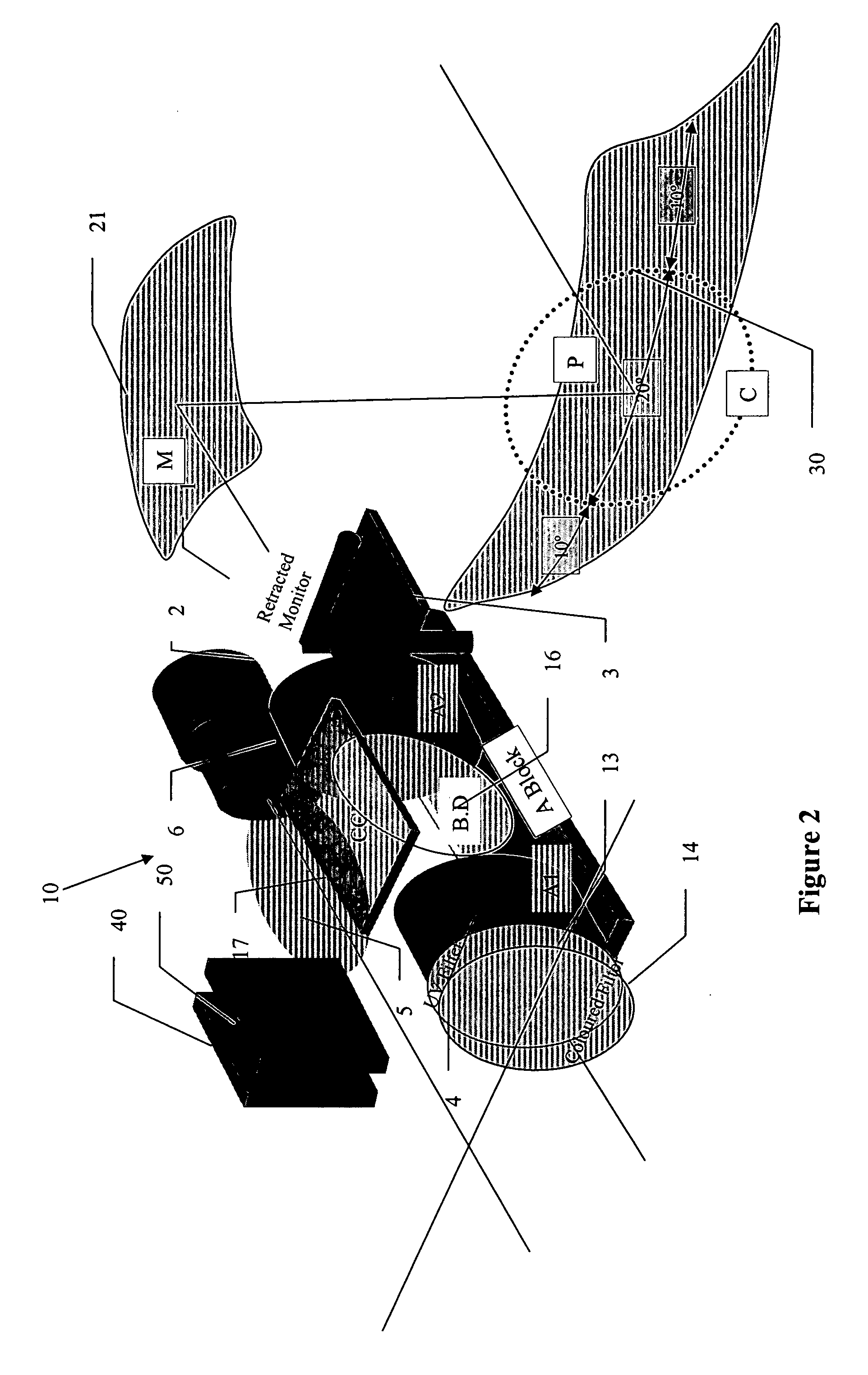
[0063] The device is composed of a movable unit (10) fulfilling the image analysis and filtration functions. This unit (10) can occupy two positions: night-time (FIGS. 1 and 4) and daytime (FIGS. 2, 3 and 5).

[0064] In the two cases of use, the final image is seen at infinity in the optical system 20 / 30.

[0065] The night-time vision function comprises a camera (1) receiving an image filtered by an optical module for filtration of the incident beam (6) contained in the unit (10), a red filter (5) and a monitor (3) comprising a screen on which the processed image forms.

[0066] The “daytime vision” function comprises an input lens (4) and a filtration system (6) provided with a feedback-controlled coronagraph (7). The optical input unit has an angular field of approximately 400. Apart from the lenses (11), it contains a first polariser (12) for the LCD matrix providing the first polarisation and the dis...


PUM


Abstract

A driving aid device for a vehicle comprises a means for imaging and a means for projecting a virtual image in a field of vision of a driver, an opaque screen, arranged in the field of view of the driver, for the formation of a virtual image focused at infinity in the field of vision of the driver of the vehicle, and further comprises means for filtration of zones of high luminous intensity.

Description

BACKGROUND OF THE INVENTION [0001] (1) Field of the Invention [0002] The present invention concerns the field of driving assistance and more particularly equipment intended to improve vision in vehicles. [0003] (2) Prior Art [0004] Various solutions are known in the prior art, generally based on “head-up” vision systems. [0005] Thus the patent EP0686865 describes a night vision system for a motorised vehicle comprising an infrared camera mounted on the vehicle in order to examine a scene on a roadway in front of the vehicle and to produce a video signal representing a thermal network of the scene. A head-up display device coupled to the video signal produces a virtual signal having a one-to-one size ratio with the images of the actual roadway scene seen by the vehicle driver. The head-up display device comprises a mixer in the field of view of a driver of the vehicle, a video display device for emitting a signal based on the video signal, and an aspherical mirror for reflecting the ...

Claims


Application Information

Patent Timeline
IPC IPC(8): H04N7/18H04N7/00H04N9/47B60R1/00B60R11/04G02B13/14G02B27/01
CPCB60R1/00B60R11/04B60R2300/106B60R2300/205B60R2300/302B60R2300/8053G02B13/14G02B27/01B60R1/23
Inventor CHRETIEN, JEAN-LOUP
Owner TIETRONIX OPTICS
Learn More