Optical filter and image pickup apparatus having the same
- Summary
- Abstract
- Description
- Claims
- Application Information
AI Technical Summary
Benefits of technology
Problems solved by technology
Method used
Image

Examples
embodiment 1
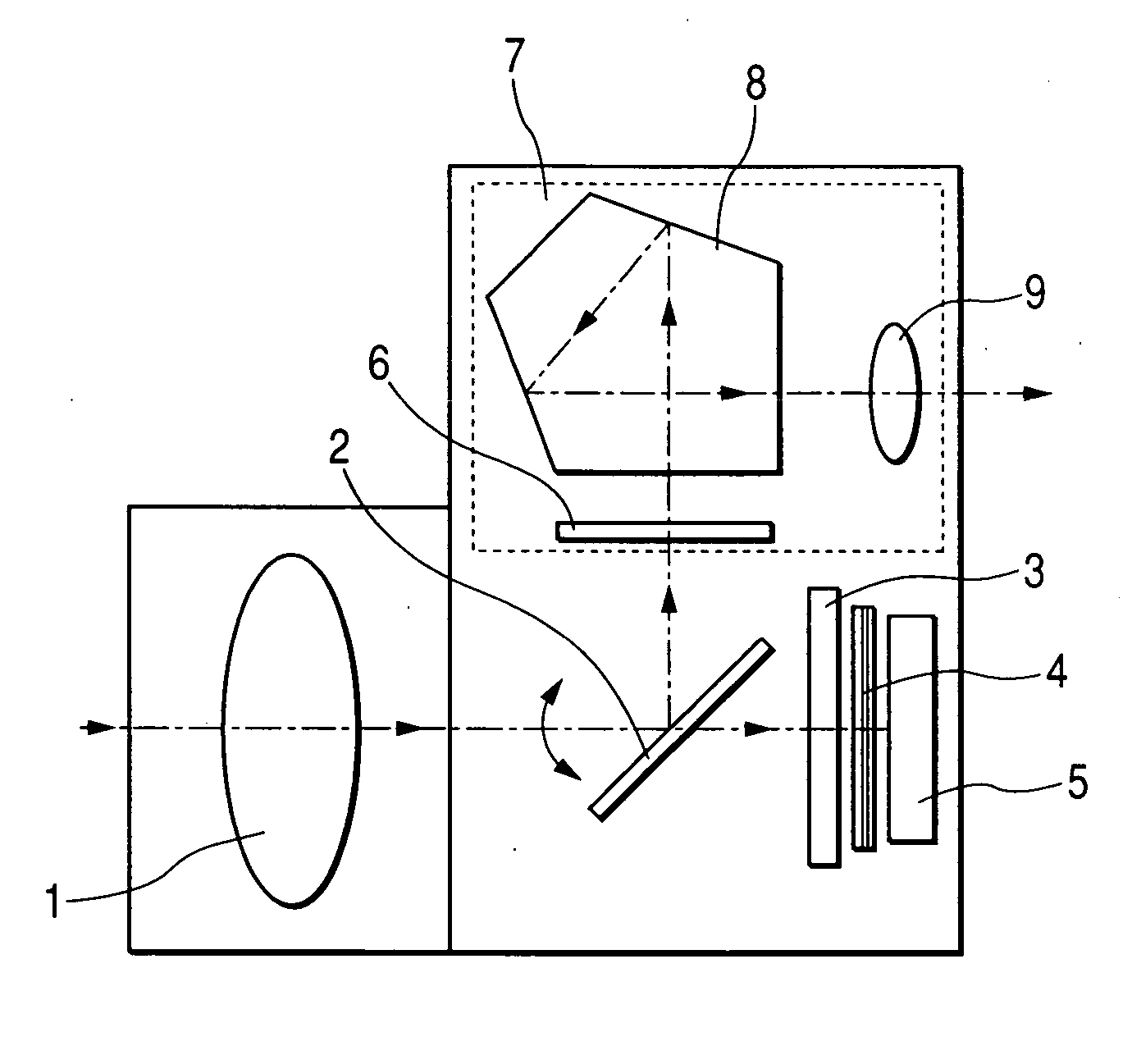
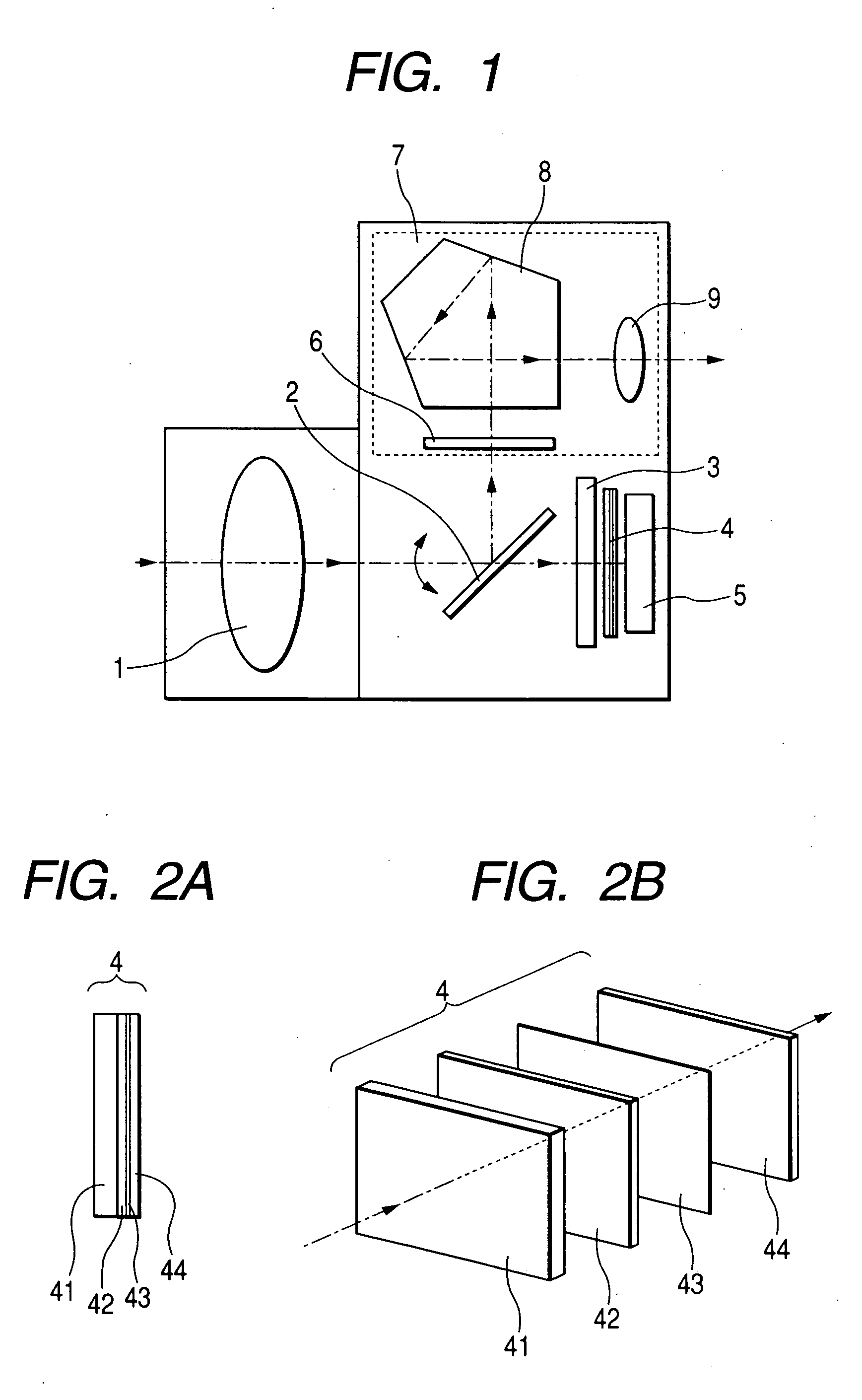
[0034]FIG. 1 is a cross-sectional view of the essential portions of a single lens reflex camera (image pickup apparatus) having an optical filter according to Embodiment 1.
[0035] In FIG. 1, the reference numeral 1 designates a photo-taking optical system as an interchangeable photo-taking lens. The reference numeral 2 denotes a pivotally movable mirror (quick return (QR) mirror) adapted to be pivotally moved as indicated by arrow A during photographing and retracted from the optical path of the photo-taking optical system 1. The reference numeral 3 designates a focal plane shutter which mechanically limits an exposure time. The reference numeral 4 denotes an optical filter according to the present invention. The optical filter 4 is disposed in the image side optical path of the photo-taking optical system 1, and is composed of a plurality of optical members which will be described later joined together. The reference numeral 5 designates an image pickup element (a solid-state image...
embodiment 2
[0065]FIGS. 6A and 6B are illustrations of an optical filter according to Embodiment 2, FIG. 6A being a cross-sectional view of the essential portions thereof, and FIG. 6B being an exploded perspective view.
[0066] The difference of the present embodiment from the aforedescribed Embodiment 1 is that the optical filter 14 is constituted by a wavelength selective member 71, first birefringence film 72, a quartz phase plate 73 and second birefringence film 74 joined together in the named order from the light incidence side to the light emergence side. In the other points, the construction and optical action of the present embodiment are substantially similar to those of Embodiment 1, whereby a similar effect is obtained.
[0067] That is, in FIGS. 6A and 6B, optical thin film (dielectric material vapor-deposited film) for intercepting the harmful lights of the near ultraviolet rays and the near infrared rays is vapor-deposited on the surface (light passing surface) of a color glass filte...
embodiment 3
[0071]FIGS. 7A and 7B are illustrations of an optical filter according to Embodiment 3, FIG. 7A being a cross-sectional view of the essential portions of the optical filter, and FIG. 7B being an exploded perspective view of the optical filter.
[0072] The difference of the present embodiment from the aforedescribed Embodiment 1 is that the optical filter 24 is constituted by a wavelength selective member 81, first birefringence film 82, and phase film 83 and second birefringence film 84 being joined together in the named order from the light incidence side (object side). In the other points, the construction and optical action of the present embodiment are substantially similar to those of Embodiment 1, whereby a similar effect is obtained.
[0073] That is, in FIGS. 7A and 7B, reference numeral 81 denotes the wavelength selective member, and optical thin film (dielectric material vapor-deposited film) for intercepting the harmful lights of the near ultraviolet rays and the near infrar...
PUM
 Abstract
Description
Claims
Application Information
 - R&D Engineer
- R&D Manager
- IP Professional
- Industry Leading Data Capabilities
- Powerful AI technology
- Patent DNA Extraction
Browse by: Latest US Patents, China's latest patents, Technical Efficacy Thesaurus, Application Domain, Technology Topic.
© 2024 PatSnap. All rights reserved.Legal|Privacy policy|Modern Slavery Act Transparency Statement|Sitemap