Process and device for cooling inorganic pigments

a technology of inorganic pigments and cooling devices, which is applied in the direction of titanium compounds, indirect heat exchangers, lighting and heating apparatus, etc., can solve the problems of affecting heat exchange, affecting the efficiency of heat exchange in the conduit, and only partially removing deposits from the inside surface of the scouring media

Inactive Publication Date: 2006-06-22
MILLENNIUM INORGANIC CHEM
View PDF3 Cites 7 Cited by
  • Summary
  • Abstract
  • Description
  • Claims
  • Application Information

AI Technical Summary

Benefits of technology

[0012] The present invention provides devices and methods for making inorganic pigments and particles. The methods and devices include those suitable for improved cooling of gases and particulates during and after the formation of inorganic pigments and particles. The methods and devices are particularly suitable for forming titanium dioxide particles.

Problems solved by technology

Typically, scouring media only partially remove deposits from the inside surfaces of the conduit.
To the extent that deposits on the conduit surface are not removed, these deposits interfere with heat exchange.
For example, as deposits adhere to the inner surface of the conduit, heat exchange in the conduit becomes less and less efficient, which adversely affects the ability of the titanium dioxide to cool in a satisfactory manner.
This in turn leads to a possible decline in quality of the titanium dioxide particles.
Although such heat exchangers can be more effective heat exchangers than those lacking such abrupt bends, they can be somewhat disadvantageous due to rapid wear from the large angle of the bend.
This wear can result in high maintenance costs.
Unfortunately, tubular heat exchangers that merely have protuberances, depressions, spiraling vanes, or recesses disposed on their internal surfaces, have certain disadvantages.
The features on the internal surfaces can serve to promote build-up of deposits at the location of these features, and can interfere with effective scouring of the internal surface of the heat exchanger.
These disadvantages can reduce heat transfer efficiency.
These features may also add significant costs to the construction of a heat exchanger.
Unfortunately, although it is desirable to reduce the amount of scouring media used in a heat exchanger, excessive use of scouring media can adversely affect the quality of inorganic pigment particles.

Method used


Image

  • Process and device for cooling inorganic pigments
  • Process and device for cooling inorganic pigments
  • Process and device for cooling inorganic pigments

Examples


example 1

Trial With a Helical Conduit Having a Three Degree Helix Angle

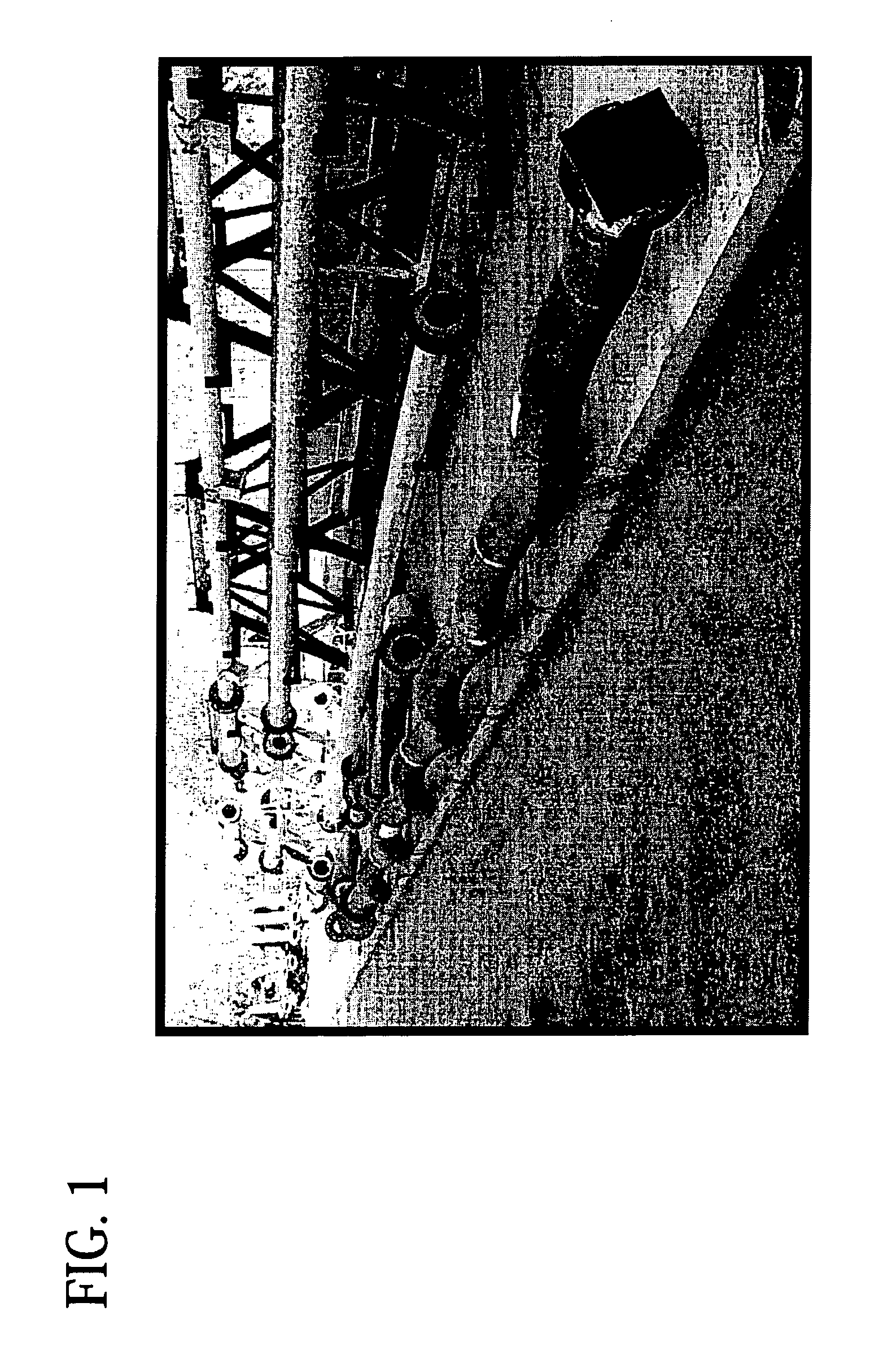
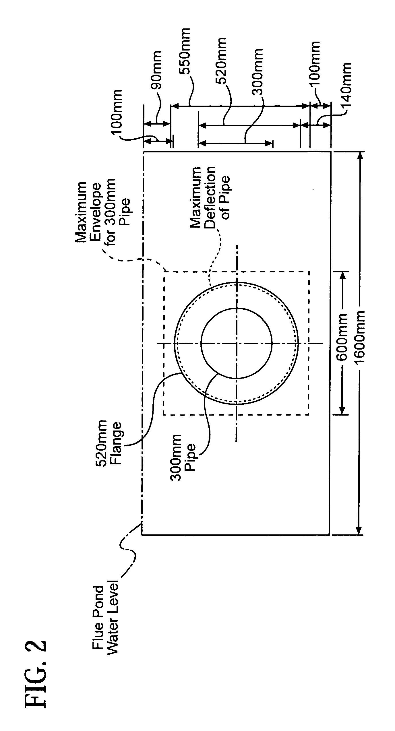
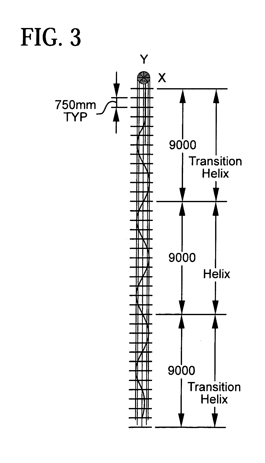
[0073] A helical conduit made from a 27.5 meter-long flue pipe with a 300 mm diameter, having a constant helix angle of 3 degrees, with three helical bends that were each complete 360 degree spiral turns was installed in a heat exchanger in a flue pond. The heat exchanger was connected directly to the outlet of an oxidation reactor. The heat exchanger was made up of several loops of pipes immersed in cooled water and the helical conduit was installed at the first length of the second loop. The helical conduit removed an additional 83 kJ / s of heat as compared with a straight conduit of the same nominal length in the same position, rendering the helical conduit about 21.6% more efficient than the straight conduit. “Straight” or “nominal” length refers to the length of a helix or helical pipe. If uncoiled, the pipe would be longer by about 0.25 m per helix. The furthest deviation of the helix was 100 mm from the center of t...

example 2

Scrub Salt Usage

[0077] Average data for scrub salt usage during runs with and without a helical pipe are displayed in Table II.

TABLE IIAverage Scrub Salt UsageRunRate (tph)NaCl (%)GradeHelical or Straight111.42.29Neutral toneStraight pipe210.473.48Blue toneHelical pipe311.302.32Neutral toneHelical pipe411.002.13Neutral toneHelical pipe510.402.59Blue toneHelical pipe611.331.91Neutral toneHelical Pipe79.241.29Neutral toneHelical Pipe89.391.93Blue toneHelical Pipe910.241.73Neutral toneHelical Pipe1010.272.31Blue toneHelical Pipe119.882.57Blue toneStraight Pipe1211.272.22Neutral toneStraight pipe

Run number describes runs for this specific study described in this table.

[0078] Srub salt usage was about 0.3 to 0.5% lower for the neutral tone run. Variation of NaCI scrub salt and rate on a daily basis was measured for nine months with the helical conduit in place, and averaged about 15% less than when using a heat exchanger having no helical conduit when normalized to reactor rate.

[007...

example 3

Scouring, Wear, and Flow Resistance Using Helical Pipe

[0080] The helical pipe was removed between Runs 3 and 4 in Table II, and a video was taken on the interior wall of the helical pipe. The video traversed the whole length. It showed that the scrub salt scoured mainly the bottom quarter to fifth of the wall forming a faintly distinct path. The path of the scouring did follow the helical profile and became slightly more prominent at the most outward points / bends. This indicated the helical pipe should have more area for heat transfer and so should be more efficient to remove heat from the flow stream.

[0081] Thickness measurements were made on several selected locations (perceived to have high wear) when the helical pipe was first taken out. No decrease in thickness or wear occurred. The same measurement was taken when the helical pipe was removed from the flue pond following 10 months of continuous service. The wear was negligible.

[0082] From the flue pipe differential pressure ...


PUM

PropertyMeasurementUnit
helix angleaaaaaaaaaa

Abstract

The present invention provides articles of manufacture and methods for making inorganic pigments. In one embodiment, the present invention provides a method for making titanium dioxide, said method comprising: (a) reacting titanium tetrachloride with oxygen in the presence of heat to produce titanium dioxide; and (b) cooling the titanium dioxide in a conduit having a helix, wherein said helix comprises at least one helical bend. Preferably the conduit comprises at least three helical bends, wherein the helix comprises at least three 360 degree spiral turns, and wherein the helix comprises an angle of from one to ten degrees. In a second embodiment, the present invention also provides a helical pipe for manufacturing pigment, comprising a conduit for receiving an inorganic pigment, wherein said conduit comprises a helix and wherein said conduit is capable of withstanding temperatures greater than about 650° C.

Description

RELATED APPLICATION [0001] This application claims the benefit of Provisional Application 60 / 632,246 filed Nov. 30, 2004.BACKGROUND OF THE INVENTION [0002] The present invention relates to methods and devices for making titanium dioxide and other inorganic pigments. [0003] One well known method of making titanium dioxide is the chloride process. According to this method, titanium tetrachloride and oxygen, in gaseous form, are mixed in a reactor at high flow rates. The reactor is operated at a high temperature, which facilitates the formation of particulate titanium dioxide and gases. These products are subsequently cooled as they pass through a conduit that is typically a tubular heat exchanger which may, for example, be immersed in a flue pond to facilitate heat exchange. [0004] In order to improve the efficiency of chloride processes, a scouring medium can be added to the heat exchanger to remove products that adhere to the inside surfaces of the conduit. A variety of scouring med...

Claims


Application Information

Patent Timeline
Patent Type & Authority Applications(United States)
IPC IPC(8): C09C1/36C01G23/047
CPCB01J19/0013B01J19/243C01G23/07C01G23/075F28D1/0213F28D7/024
Inventor SARRACINI, ROBERT J.WONG, JOHN Y.GARTON, SHANE R.
Owner MILLENNIUM INORGANIC CHEM
Why Eureka
Try Eureka