
Lensed fiber array for sub-micron optical lithography patterning

a fiber array and sub-micron optical lithography technology, applied in the field of image writing and exposure systems, can solve the problems of manufacturing difficulties, operational difficulties, and increased cost of fabrication, inspection and handling of masks for use in conventional exposure systems, and achieve the effect of avoiding the need for precise alignment of multiple elements and avoiding the need for masks

Inactive Publication Date: 2006-06-22
3M INNOVATIVE PROPERTIES CO
View PDF11 Cites 33 Cited by
  • Summary
  • Abstract
  • Description
  • Claims
  • Application Information

AI Technical Summary

Problems solved by technology

As the minimum feature size of integrated circuits continues to shrink and the complexity of the patterns continues to grow, the cost of fabrication, inspection, and handling of masks for use in conventional exposure systems continues to rise.
The high tolerance requirement for the optics presents manufacturing difficulties and the precise alignment requirement for the multiple elements presents operational difficulties.
Problems also arise because the multi-element optics must provide dimensional stability over large distances between optical and mechanical components to maintain resolution, focus, and accuracy.
As the feature size decreases, however, system alignment of the conventional maskless lithography system becomes more difficult and problems arise due to aberrations, such as, spherical aberration, coma, and distortion.

Method used


Image

  • Lensed fiber array for sub-micron optical lithography patterning
  • Lensed fiber array for sub-micron optical lithography patterning
  • Lensed fiber array for sub-micron optical lithography patterning

Examples


Embodiment Construction

[0020] Reference will now be made in detail to the exemplary embodiments, examples of which are illustrated in the accompanying drawings. Wherever possible, the same reference numbers will be used throughout the drawings to refer to the same or like parts.

[0021] As used herein, the term “pitch” refers to a center-to-center distance between two lines written in a radiation sensitive material by adjacent waveguides, such as, for example, optical fibers.

[0022] As used herein, the terms “detector” and “optical detector” refer to any component or system of components that can detect light including, for example, a charged coupled device (CCD), a photodiode or a photodiode array, a complimentary metal-oxide semiconductor (CMOS) sensor, a CMOS array, and a photomultiplier tube (PMT).

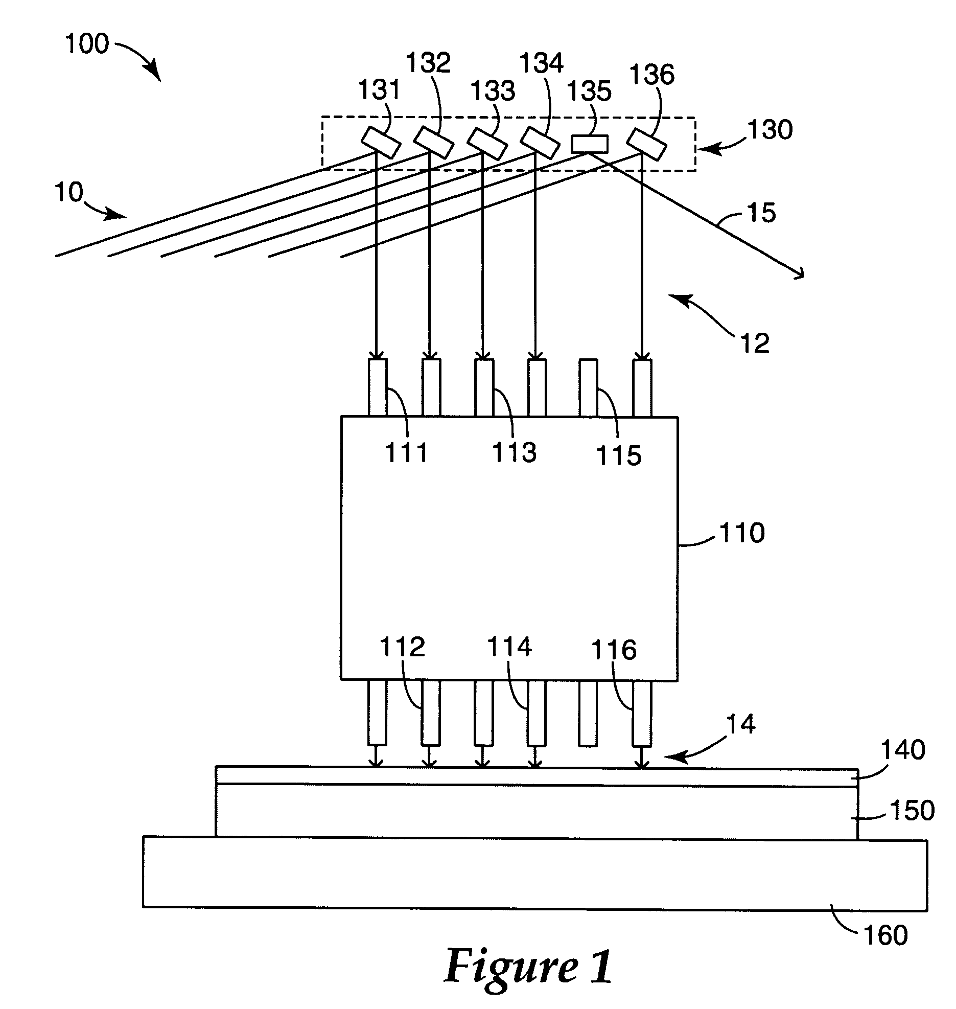
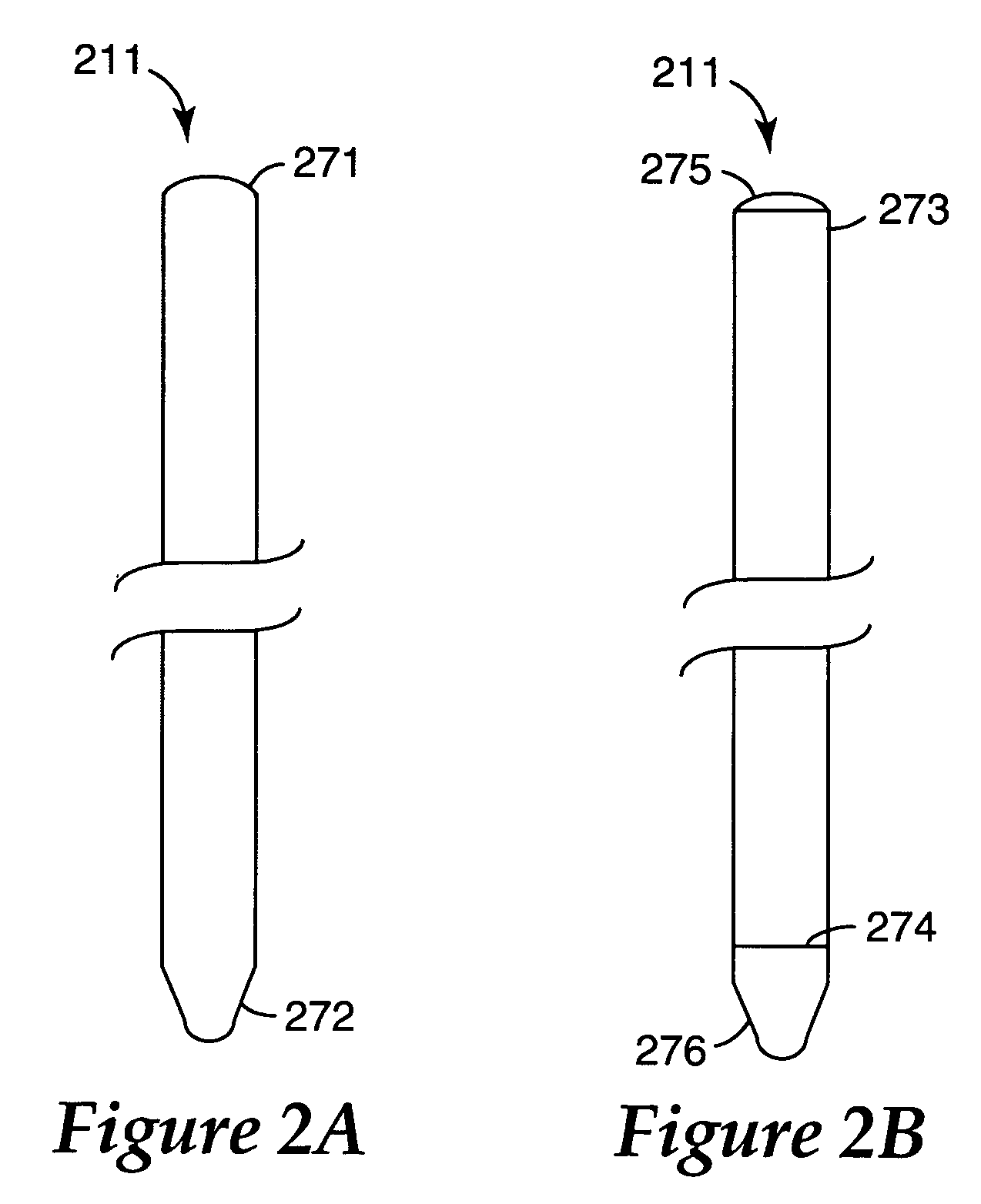
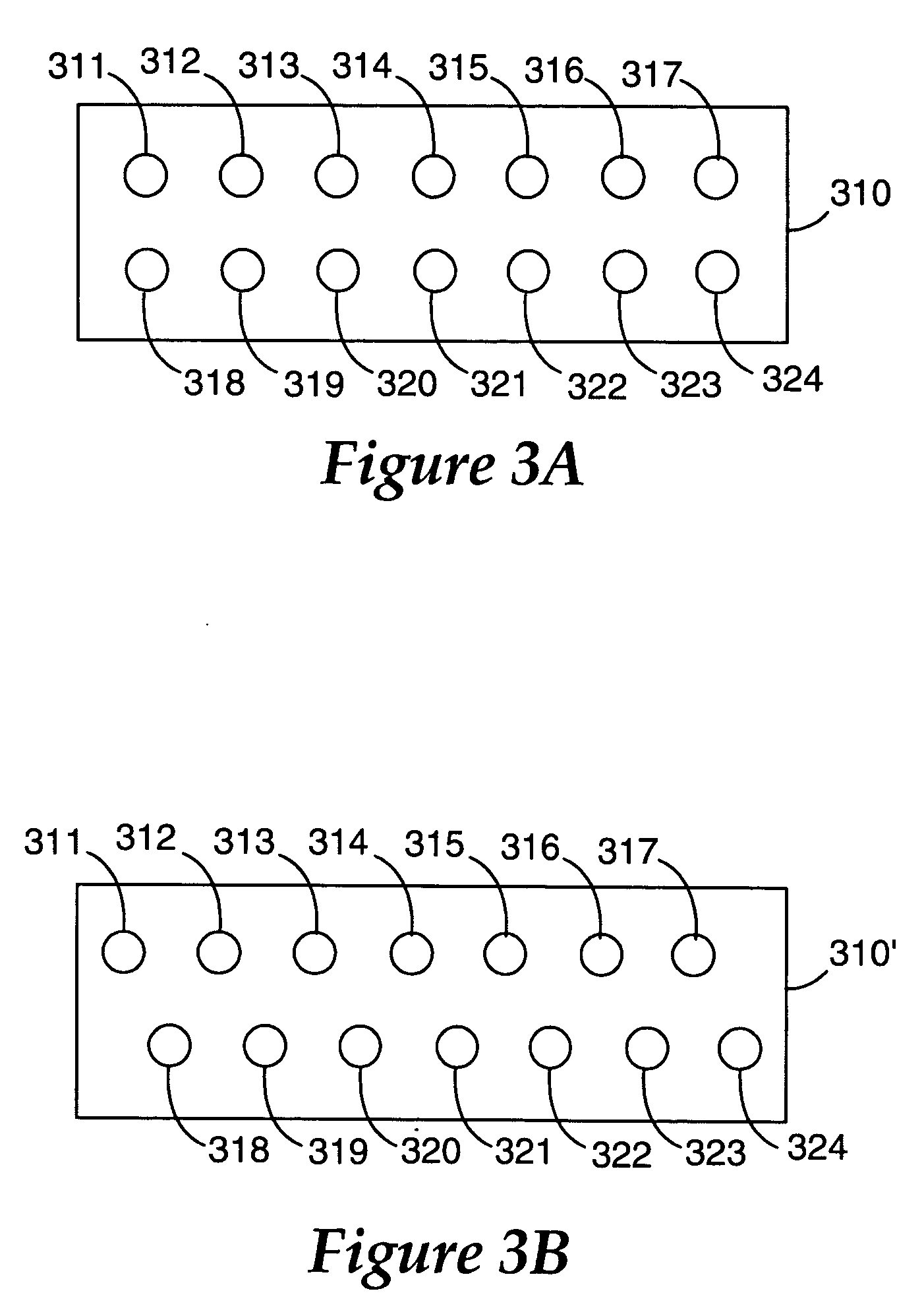
[0023]FIGS. 1-9 disclose exposure systems for image writing in accordance with exemplary embodiments of the present teachings. The exemplary exposure systems include a modulator to modulate light and a waveg...


PUM

PropertyMeasurementUnit
velocityaaaaaaaaaa
photosensitiveaaaaaaaaaa
feature sizeaaaaaaaaaa

Abstract

In accordance with various embodiments, there is an exposure system for writing a pattern on a photosensitive material. The exposure system can include a waveguide array and a light modulator. The waveguide array can include a plurality of optical fibers that focuses light on the radiation sensitive material. The light modulator can modulate the light coupled into the plurality of optical fibers. Exemplary exposure systems can reduce aberrations due to coma and distortion, and provide improved alignment.

Description

FIELD OF THE INVENTION [0001] The invention generally relates to methods for image writing and exposure systems for image writing and, more particularly to methods and apparatus for maskless lithography. BACKGROUND OF THE INVENTION [0002] As the minimum feature size of integrated circuits continues to shrink and the complexity of the patterns continues to grow, the cost of fabrication, inspection, and handling of masks for use in conventional exposure systems continues to rise. Conventional exposure systems, such as, for example, optical lithography systems, use optical steppers to image a reticle or “mask” through a lens to create a pattern on a layer. The area to be patterned on the layer is generally much larger than the field size of the imaging lens, so multiple exposures must be made using a step-and-repeat system. Alternatively, the layer can be patterned by moving the reticle and the layer at the same time in opposite directions using a step-and-scan system. [0003] Conventio...

Claims


Application Information

Patent Timeline
Patent Type & Authority Applications(United States)
IPC IPC(8): G03B27/00G03F9/00G03C5/00
CPCG03F7/70275G03F7/70291G03F7/70308G03F7/70391
Inventor PORQUE, JEROME C.
Owner 3M INNOVATIVE PROPERTIES CO
Learn More