
Controlling temperature in catalyst regenerators

a catalyst and temperature control technology, applied in the field of regenerating catalysts, can solve the problems of reducing the ability of catalysts to function efficiently, excessively “coked” catalysts, and increasing the power and cost of air blowers

Active Publication Date: 2006-06-22
EXXONMOBIL CHEM PAT INC
View PDF17 Cites 14 Cited by
  • Summary
  • Abstract
  • Description
  • Claims
  • Application Information

AI Technical Summary

Benefits of technology

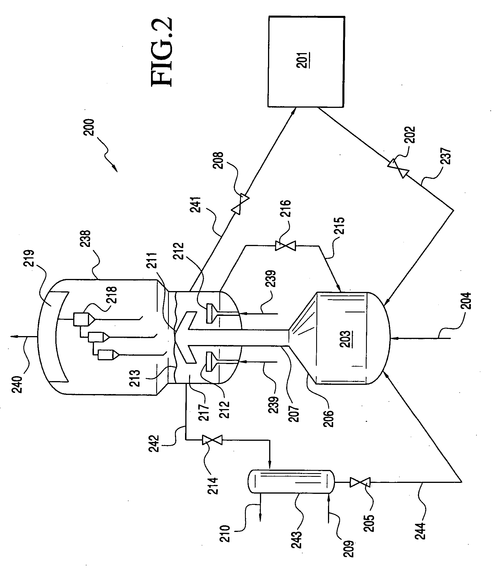
[0026] Optionally, the system further comprises a temperature control catalyst conduit for communicating regenerated catalyst from the regeneration zone directly to the mixing zone. The temperature control catalyst conduit optionally comprises a valve for controlling the flow of the regenerated catalyst communicated so as to control the temperature of the mixed catalyst in the mixing zone. As a result, the valve also acts to control the temperature of the catalyst in the regeneration zone.

Problems solved by technology

At some point, the build up of these carbonaceous deposits causes a reduction in the capability of the catalyst to function efficiently.
For example, in the OTO process, an excessively “coked” catalyst does not readily convert the oxygenate feed to light olefins.
Higher pressures are generally preferred for lowering equipment size and catalyst inventory, however, higher pressures increase air blower power and cost.
Such temperatures would cause significant damage to the catalyst regenerator and to the catalyst particles.

Method used


Image

  • Controlling temperature in catalyst regenerators
  • Controlling temperature in catalyst regenerators

Examples


Embodiment Construction

I. INTRODUCTION

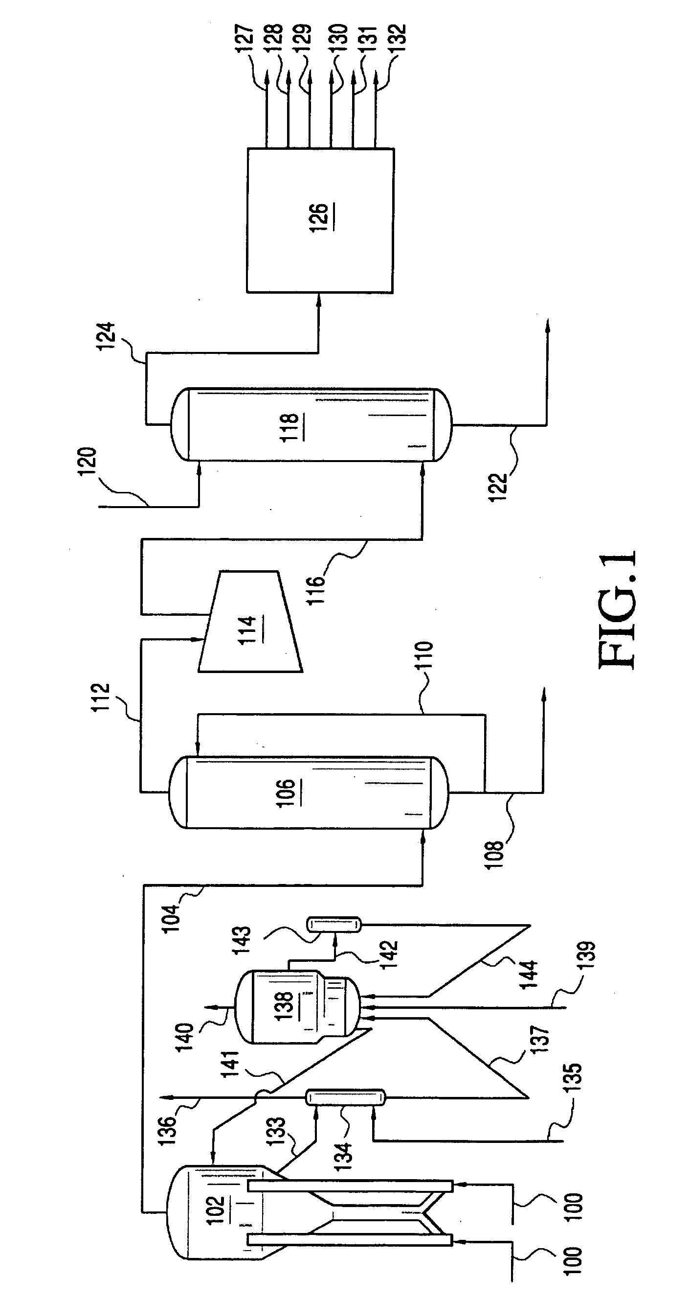
[0030] This invention relates to efficiently regenerating catalyst particles by minimizing the formation of localized “hot spots” in a regeneration zone. In one embodiment, the invention includes mixing spent catalyst from a reactor and cold catalyst from a catalyst cooler in a mixing zone and directing the mixed catalyst to the regeneration zone in a fluidized manner with a fluidizing medium. In the regeneration zone, the mixed catalyst contacts an oxygen-containing regeneration medium under conditions effective to regenerate the spent catalyst contained therein.

II. OXYGENATE TO OLEFIN REACTION SYSTEMS

[0031] As indicated above, the present invention is directed to controlling the temperature of catalyst regeneration, preferably in an OTO reaction process. OTO reaction systems will now be described in greater detail. As used herein, “reaction system” means a system comprising a reactor, a catalyst cooler, optionally a catalyst regenerator, and optionally a catalyst...


PUM

PropertyMeasurementUnit
temperatureaaaaaaaaaa

Abstract

This invention relates to efficiently regenerating catalyst particles by minimizing the formation of localized “hot spots” and “cold spots” in a regeneration zone. In one embodiment, the invention includes mixing spent catalyst from a reactor and cold catalyst from a catalyst cooler in a mixing zone and directing the mixed catalyst to the regeneration zone in a fluidized manner with a fluidizing medium. In the regeneration zone, the mixed catalyst contacts an oxygen-containing regeneration medium under conditions effective to regenerate the spent catalyst contained therein.

Description

CROSS REFERENCE TO RELATED APPLICATIONS [0001] This application claims the benefit of Provisional Application No. 60 / 638,766 filed Dec. 22, 2004, the disclosure of which is fully incorporated herein by reference.FIELD OF THE INVENTION [0002] The present invention relates to regenerating catalyst. More particularly, the invention relates to controlling catalyst temperature during the regeneration process. BACKGROUND OF THE INVENTION [0003] Light olefins, defined herein as ethylene and propylene, serve as feeds for the production of numerous chemicals. Olefins traditionally are produced by petroleum cracking. Because of the limited supply and / or the high cost of petroleum sources, the cost of producing olefins from petroleum sources has increased steadily. [0004] Alternative feedstocks for the production of light olefins are oxygenates, such as alcohols, particularly methanol, dimethyl ether, and ethanol. Alcohols may be produced by fermentation, or from synthesis gas derived from nat...

Claims


Application Information

Patent Timeline
Patent Type & Authority Applications(United States)
IPC IPC(8): B01J38/30
CPCB01J29/90B01J38/30B01J38/32C07C1/20C07C11/02Y02P20/584
Inventor CUNNINGHAM, BRIAN A.STEFFENS, TODD R.BEECH, JAMES H. JR.WALTER, RICHARD E.
Owner EXXONMOBIL CHEM PAT INC
Learn More