Medical device with elastomeric bulb

a technology of elastomeric bulbs and medical devices, which is applied in the direction of balloon catheters, catheters, stents, etc., can solve the problems of reducing the resistance to escape water, affecting the flow rate of fluid, so as to improve the flow rate and facilitate the arrangement of the sleeves. , the effect of reducing the rate of fluid loss

Inactive Publication Date: 2006-06-22
CR BARD INC
View PDF22 Cites 16 Cited by
  • Summary
  • Abstract
  • Description
  • Claims
  • Application Information

AI Technical Summary

Benefits of technology

[0009] An object of the present invention is to achieve greater certainty, during the manufacture of pre-filled Foley catheters, that the catheter will deliver a satisfactory shelf life.
[0029] In this connection, inclusion of the fluid drain coupling alongside the fluid supply element inside the sleeve will not appreciably reduce the effectiveness of the sleeve in slowing down the rate of loss of fluid through the wall of the reservoir bulb. This is because both elements can be made with surface topographies made up of gentle curves and out of relatively soft materials which therefore deform relatively easily to conform to the embrace of a sleeve applied using shrink wrapping techniques. However, placing the sleeve around both the fluid drain coupling and the fluid supply element can deliver the technical effect that the device is packed in a more compact and orderly way, which facilitates further manufacturing processing and packaging of the device, and improves the visual attractiveness of the device to those who purchase and use it. It also provides a packaging over the fluid drain coupling (which in present devices is not sleeved) and a vehicle for carrying printed matter.

Problems solved by technology

Achievement of a satisfactory shelf-life for pre-filled Foley catheters has proved to be a challenge.
Nevertheless, residual problems remain, some of which are discussed in U.S. Pat. No. 3,602,226.
One such problem is that the coating tends to crack.
This reduces the resistance to escape of water and can adversely affect appearance.
Another problem is to achieve satisfactory continuity of the coating around the clip at the distal end of the bulb, and the customary filler valve at the proximal end of the bulb.
The thickness of latex catheters made by a conventional dipping process is always liable to vary, and this variation can prejudice the goal of reliable sealing with an external moulded clip.
With a conventional U-shaped one-piece clip, and latex walls of uncertain thickness, there is some potential for the clip to damage the latex lumen wall.

Method used


Image

  • Medical device with elastomeric bulb
  • Medical device with elastomeric bulb
  • Medical device with elastomeric bulb

Examples


Embodiment Construction

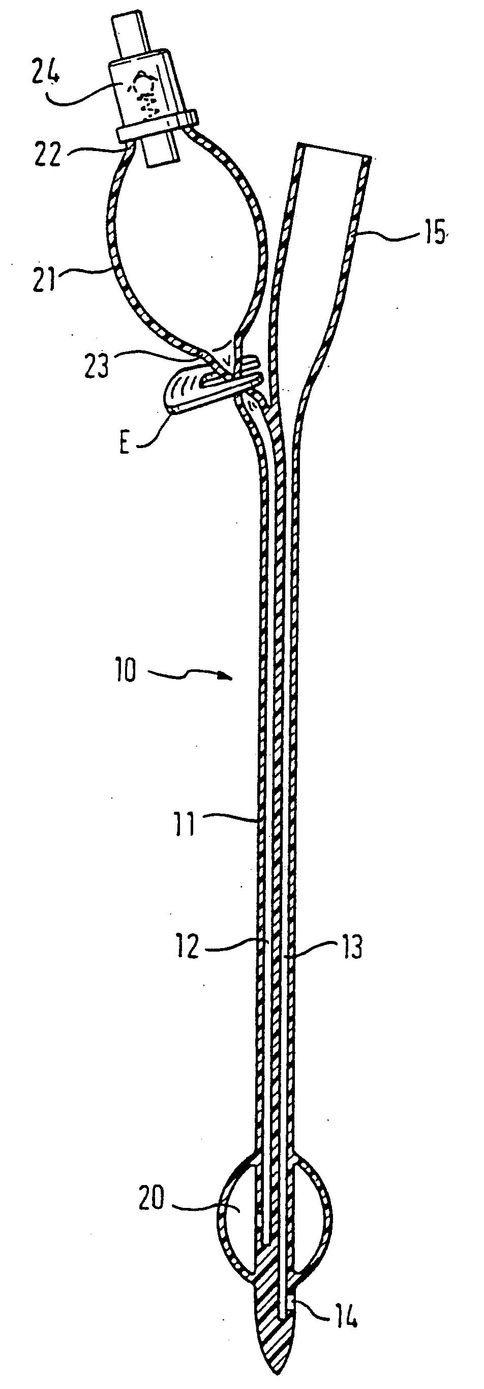
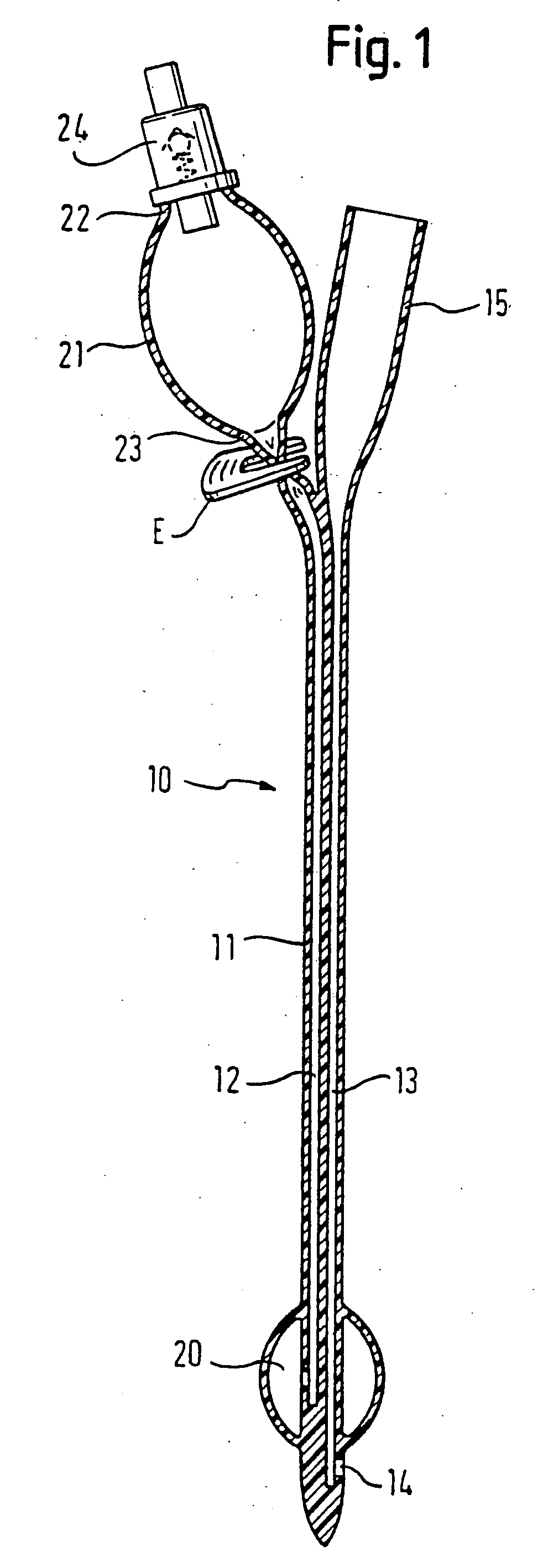
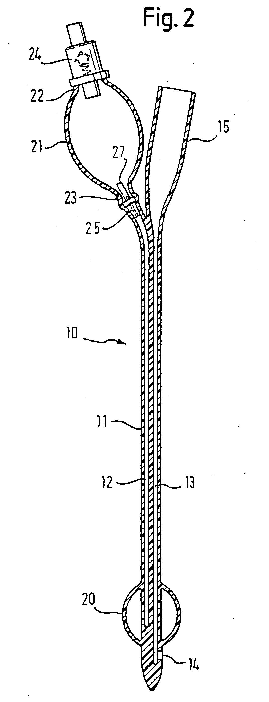
[0043]FIG. 1 shows a known pre-filled Foley catheter. The catheter 10 comprises a shaft 11 of latex rubber which defines a balloon inflation lumen 12 and a drainage lumen 13. The drainage lumen 13 extends from a distal drainage port 14 to a drainage bag coupling element 15 at the proximal end of the catheter. The inflation lumen 12 connects a chamber 20 at the distal end of the catheter, but proximal of the drainage port 14, with a reservoir bulb 21 at the proximal end of the device. In FIG. 1, both of the balloon 20 and bulb 21 are shown inflated, for the sake of clarity, but those skilled in the art will appreciate that the sterile water within the bulb 21 is not sufficient simultaneously to fill both the bulb and the balloon. The reality is that, when the bulb 21 is full, the balloon 20 is not yet inflated and, when the balloon 20 is fully inflated, the bulb 21 is deflated.

[0044] The bulb 21 has a proximal end 22 and a distal end 23. At the proximal end 22 is a conventional one-...


PUM

PropertyMeasurementUnit
inner diameteraaaaaaaaaa
diameteraaaaaaaaaa
diameteraaaaaaaaaa

Abstract

In a pre-filled Foley catheter for urine drainage, the conventional clip for releasing sterile water from a bulb (21) at the proximal end of the catheter, to fill the anchor bulb (20) at the distal end of the device, is replaced by a plug (25) which has an annular portion connected to a thin stem (27) by a circle of weakness. Snapping the stem (27) from the annulus provides a tactile signal through the opaque latex lumen that the catheter has been actuated. There is no separate clip to be disposed of. The interface between the latex and the plug remains undisturbed. Further improvement in the shelf- life and convenience of use of the catheter is delivered by the use of a sleeve, which can be of shrink-wrap material, around the bulb (21) and optionally also around the drain coupling (15) of the catheter. Apparatus for placing the plug and the sleeve is also described.

Description

RELATED APPLICATIONS [0001] This application is a divisional application of U.S. Ser. No. 09 / 720,309, filed Apr. 9, 2001, which is a 371 of PCT / EP99 / 04421, filed Jun. 25, 1999 which claims priority of PCT / EP98 / 03892, filed Jun. 25, 1998.TECHNICAL FIELD [0002] A pre-filled Foley catheter can be regarded as one example of a medical device with a proximal end and a distal end, an elastomeric bulb at the proximal end for storing fluid under pressure and a fluid acceptor at the distal end and a lumen connecting the bulb and the acceptor for flow of fluid from the bulb to the acceptor when the device is used, and including a control device at the proximal end of the lumen to prevent said fluid flow until said flow is desired. It is in this class of medical devices that the present invention is to be found. BACKGROUND [0003] The Foley catheter is a catheter device usually made out of elastomeric material, which is for urine drainage and which is installed with its distal end in the bladder...

Claims


Application Information

Patent Timeline
Patent Type & Authority Applications(United States)
IPC IPC(8): A61M1/00A61F2/958A61M39/22A61M25/00B25B27/10
CPCA61M25/0017A61M25/002Y10T29/494A61M25/1018A61M2039/222A61M25/10A61M25/10183
Inventor MEEK, ROGER HOWARDEVANS, DAVID
Owner CR BARD INC
Why Eureka
Try Eureka