Method and apparatus for precise positioning of an object with linear stepper motors

a linear stepper motor and precise positioning technology, applied in the direction of motor/generator/converter stopper, multiple dynamo-motor starters, motor/generator/converter stoppers, etc., can solve the problem of introducing error between the desired and actual orientation of the object moved by the motor, and limiting the precision and smoothness of the linear stepper motor. the effect of precision positioning, high precision and reduced positioning error

Inactive Publication Date: 2006-06-29
BIO RAD LAB INC
View PDF1 Cites 9 Cited by
  • Summary
  • Abstract
  • Description
  • Claims
  • Application Information

AI Technical Summary

Benefits of technology

[0013] The present invention also advantageously reduces the positioning error significantly (e.g., up to 10 times or more) without the need for any position feedback device. Moreover, the motion of the object to be moved is smoothened (made uniform) due to the absence of large repetitive error. The uniform and smooth motion may be more important in some applications (e.g., scanning of features on a slide in molecular biology applications), while the positioning precision may be more important in some other applications (e.g., precision X-Y stage in a microarrayer).
[0014] Aspects of the present invention are applicable to X-Y stages where a domain of high precision is defined as a rectangle in the X-Y plane. The present invention is also useful for precise positioning and smooth motion of an X-Y-Z assembly, including X and Y actuators that are linear stepper motors, and a Z actuator that is used for vertical positioning of the end-effector (e.g., a microarrayer printhead). High speed and acceleration are achieved in gross motion in the X-Y plane, while the Z-actuator is application dependent and may be constructed in various ways including, for example, a coil actuator (for small payloads), ball-screw stepper motor assembly (for high loads), etc. One application of an X-Y-Z assembly according to the present invention is in a microarrayer that has high precision (few microns), high speed (few meters per second), high acceleration (e.g., 1 G or higher), and low cost (there is no need for a position measuring device in the system).
[0015] The present invention also eliminates the need for physical adjustment of the home sensor position in the manufacturing process, while still achieving consistent homing towards the same full-current-in-one-coil position always.
[0016] The present invention also provides a method of homing that eliminates jerks during homing, resulting in highly repeatable homing, which is of crucial importance for precise positioning.

Problems solved by technology

It is known that linear stepper motors are limited in terms of precision and smoothness of motion due, for example, to the presence of cyclic positioning error, thermal expansion error, straightness of the actuator, and other errors due to imperfection in manufacturing of the motor.
As a consequence, an error may be introduced between the desired and actual position of the object moved by the motor, especially if the object is located at some distance from the center of the forcer.
Also, an error may be introduced between the desired and actual orientation of an object attached to the moving part of the motor (i.e., forcer 20).
However, the position of the object P that is off-centered from the ideal line of the motion (X) is affected not only by the positioning error in point C, but also the orientation error (φ), which is mostly due to imperfect straightness of the platen.
However, the construction of a lead-screw mechanism is not suitable for high speed, high-acceleration applications.
However, the cost of typical brushless DC or AC linear motor and a linear optical encoder may be prohibitively expensive and would qualify this technology for “high-end” applications.
In other words, many laboratory instruments and machines cannot afford this technology from a cost of goods standpoint.

Method used


Image

  • Method and apparatus for precise positioning of an object with linear stepper motors
  • Method and apparatus for precise positioning of an object with linear stepper motors
  • Method and apparatus for precise positioning of an object with linear stepper motors

Examples


Embodiment Construction

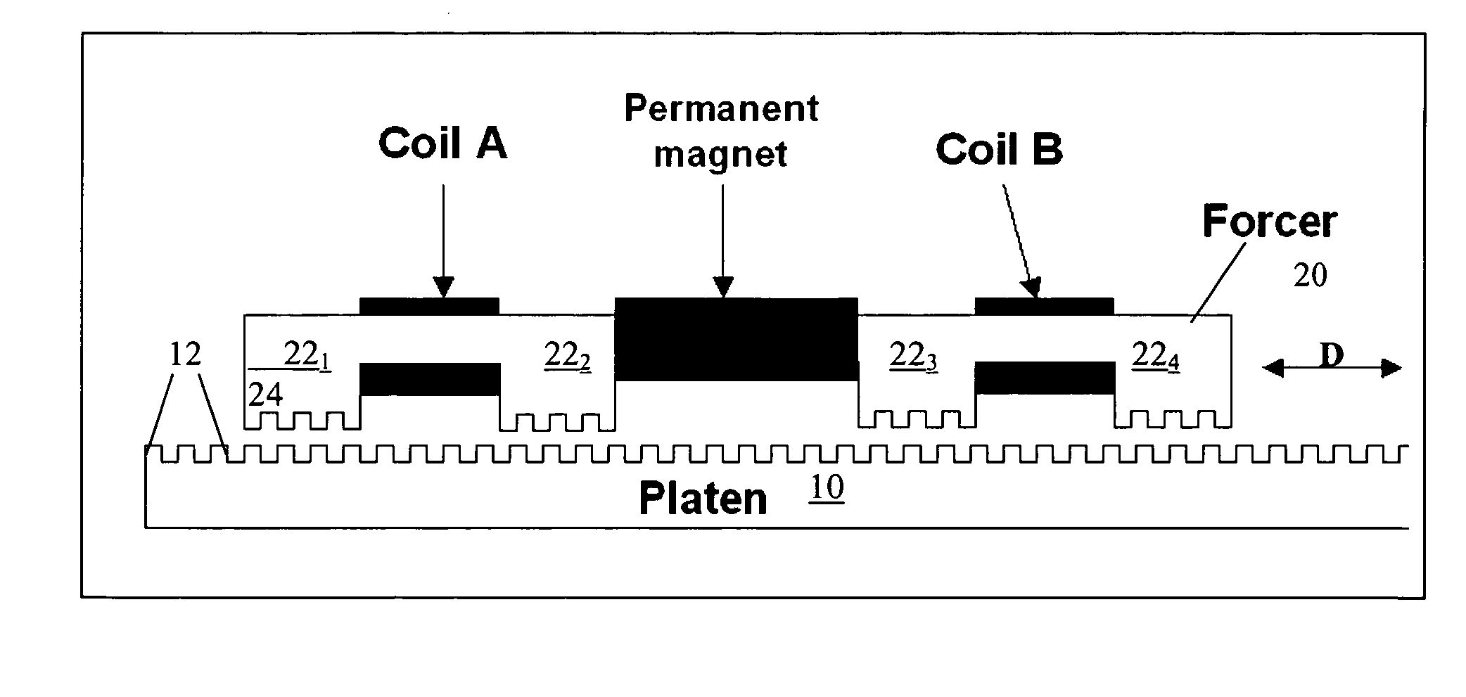
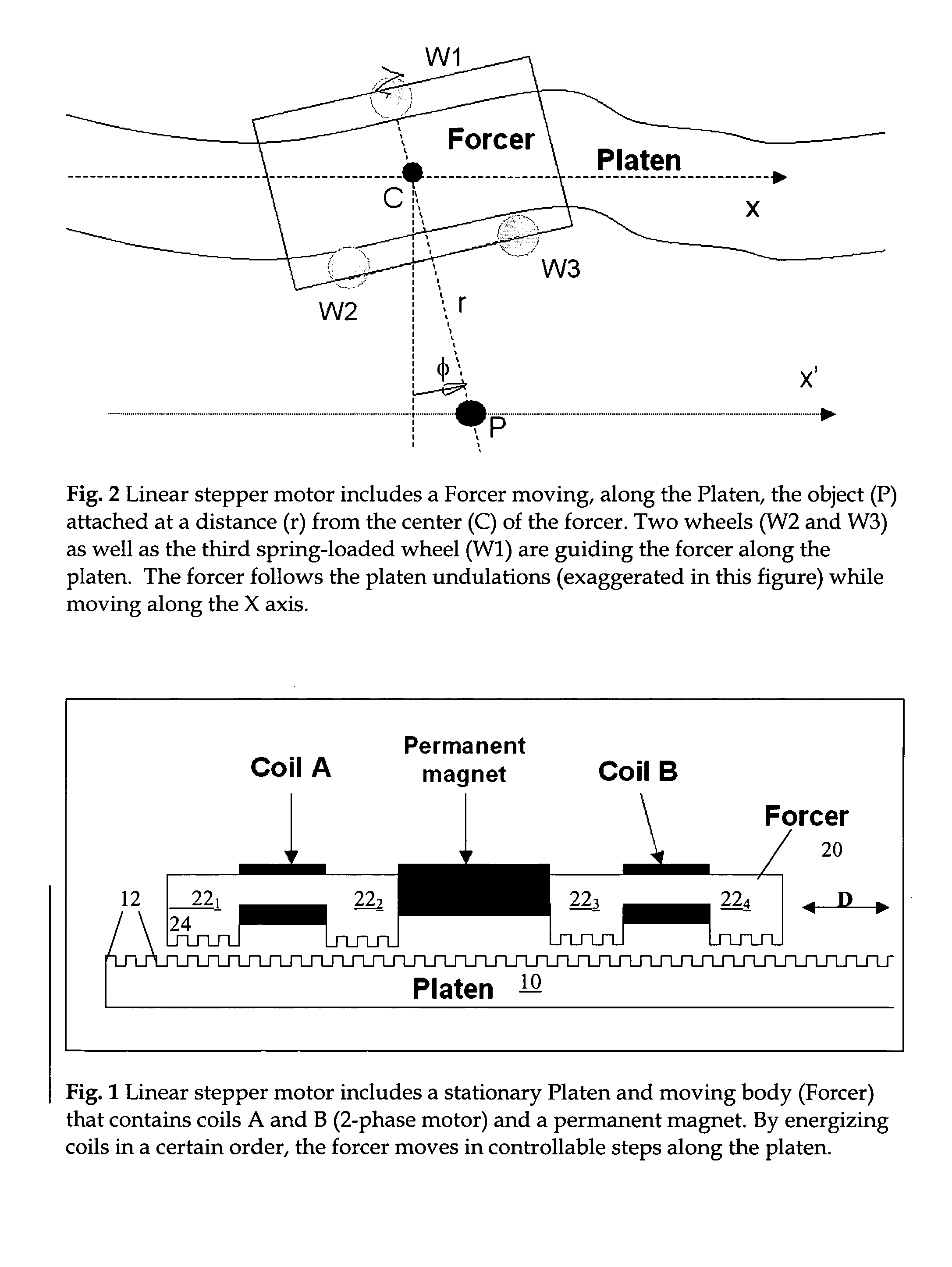
[0043] According to one embodiment, as shown in FIG. 1, a linear stepper motor includes a moving forcer 20 and a stationary platen 10. The forcer 20 includes two coils (A and B) inserted in steel cores with teeth 24 and a single permanent magnet encapsulated in an aluminum housing. The forcer 20 moves on air-bearings or wheels along the platen 10: e.g., a photo-chemically etched steel bar with teeth 12 perpendicular to the axis X in FIG. 2 (also shown as a cross-section in FIG. 1). The forcer 20 has 4 sets of teeth 24 facing the teeth 12 of the platen 10 (e.g., at a distance of 40 microns). The distance between these 4 sets of teeth is not a multiple of the platen teeth pitch, but there is an offset so that only one set of the teeth would face the platen teeth. The other sets are offset by ¼, ½, and ¾ of the pitch. By applying the electric current to the first coil (A) the first set of teeth will align with the platen teeth. When the current in A is zero, but the current in the coil...


PUM


Abstract

Methods and apparatus for precise positioning of an object using linear actuators based on linear stepper motors operating in microstepping or full step mode, a control algorithm based on compensation table, and a calibration apparatus for obtaining the compensation table.

Description

CROSS-REFERENCES TO RELATED APPLICATIONS [0001] This application claims the benefit of U.S. Provisional Application No. 60 / 632,576 (Attorney docket No. 002558-07110US), filed Dec. 1, 2004, the disclosure of which is incorporated herein by reference in its entirety.BACKGROUND OF THE INVENTION [0002] The present invention relates generally to linear stepper motors and more particularly to systems and methods for precisely positioning an object using a linear stepper motor. [0003] Linear stepper motors typically include a platen 10 and a forcer 20 as shown, for example, in FIG. 1. The platen 10 is the fixed, passive part of the motor and its length will determine the distance the motor will travel. The platen 10 typically has a number of teeth 12 equally spaced along its length, and is like the rotor in a traditional rotary stepper motor, except it is not a permanent magnet. The forcer 20 typically includes four pole pieces 22 that each have three or more teeth 24. The pitch of each to...

Claims


Application Information

Patent Timeline
Patent Type & Authority Applications(United States)
IPC IPC(8): H02K41/00
CPCH02K2201/18H02K41/033
Inventor KIRCANSKI, NENADSADRI, AMIRTIMOTIJEVIC, MILIJAXU, ZHILIANGKIRCANSKI, MANJANIKOLIC, NEVEN
Owner BIO RAD LAB INC
Why Eureka
Try Eureka