Interlayers for laminated safety glass with superior de-airing and laminating properties and process for making the same

a technology of laminated safety glass and interlayers, which is applied in the field of interlayers for laminated safety glass with superior de-airing and laminating properties and process for making the same, can solve the problems of difficult to choose an interlayer with optimal, inconvenient to obtain edge seals, and may encounter problems for laminaters

Inactive Publication Date: 2006-06-29
PERFORMANCE MATERIALS NA INC
View PDF39 Cites 66 Cited by
  • Summary
  • Abstract
  • Description
  • Claims
  • Application Information

AI Technical Summary

Benefits of technology

[0021] In one aspect the present invention is an unplasticized thermoplastic sheet useful for making safety glass laminates, wherein the sheet comprises at least one surface embossed with a regular pattern which provides relatively uninterrupted channels for de-airing in two directions, said channels having depth of less than about 20 microns, and width 30 microns to 300 microns and spaced between 0.1 mm and 1 mm apart.
[0022] In another aspect, the present invention is a glass / adhesive sheet laminate comprising at least one layer of glass and a sheet of unplasticized thermoplastic interlayer, said interlayer having at least one surface embossed with a regular pattern which provides relatively uninterrupted channels for de-airing in two directions, said channels having depth of less than about 20 micrometers (microns), and width 30 microns to 300 microns and spaced between 0.1 mm and 1 mm apart.
[0023] In still another aspect, the present invention is a process of manufacturing a laminated safety glass article comprising the steps of: (1) embossing at least one surface of an unplasticized thermoplastic interlayer with a regular pattern which provides relatively uninterrupted channels for de-airing in two directions, said channels having depth of less than about 20 microns, and width 30 microns to 300 microns and spaced between 0.1 mm and 1 mm apart; (2) laminating the embossed sheet to at least one glass surface, wherein the embossed surface of the unplasticized thermoplastic interlayer is laminated to glass.

Problems solved by technology

These are generally objectionable for end use applications where the laminate functions as a transparent article, that is, being essentially free of optical defects (e.g. relatively low-haze thus providing a transparent article without hindering visibility).
It is not an uncommon defect in laminated glass for dissolved gasses to come out of solution (form bubbles or delaminated areas between the glass / interlayer interface) as time progresses, especially at elevated temperatures experienced in automobiles, buildings and the like, often due to weather conditions and sunlight exposure.
However, laminators may encounter an issue when selecting a suitable interlayer.
It is sometimes difficult to choose an interlayer with optimal features for pre-pressing, namely, rapid air removal and proper edge seal.
However, such interlayers can make it inconvenient to obtain edge seal as more energy is generally required to compact the rough interlayer.
If the edges of the pre-press are not completely sealed, air can penetrate the edge in the autoclaving step where the pre-press is heated under high pressure, and can cause visual defects in the laminate which is commercially unacceptable.
Laminators who use vacuum for de-airing in hot environments can have added difficulty.
On the other hand, relatively smooth interlayers can lead to the edges sealing before sufficient air is removed, and can leave air trapped inside the pre-press.
Defects which occur after lamination are often more costly to rectify.
Due to these physical differences, surface patterns useful for plasticized PVB interlayer sheeting may not be ideal for ionomer interlayer sheeting, and vice versa.
However, the use of deep patterns with ionoplastic interlayers is not trouble-free.
Also, the sharper melting range of an unplasticized interlayer can lead to trapped air in the laminate.

Method used


Image

  • Interlayers for laminated safety glass with superior de-airing and laminating properties and process for making the same
  • Interlayers for laminated safety glass with superior de-airing and laminating properties and process for making the same
  • Interlayers for laminated safety glass with superior de-airing and laminating properties and process for making the same

Examples


example 1

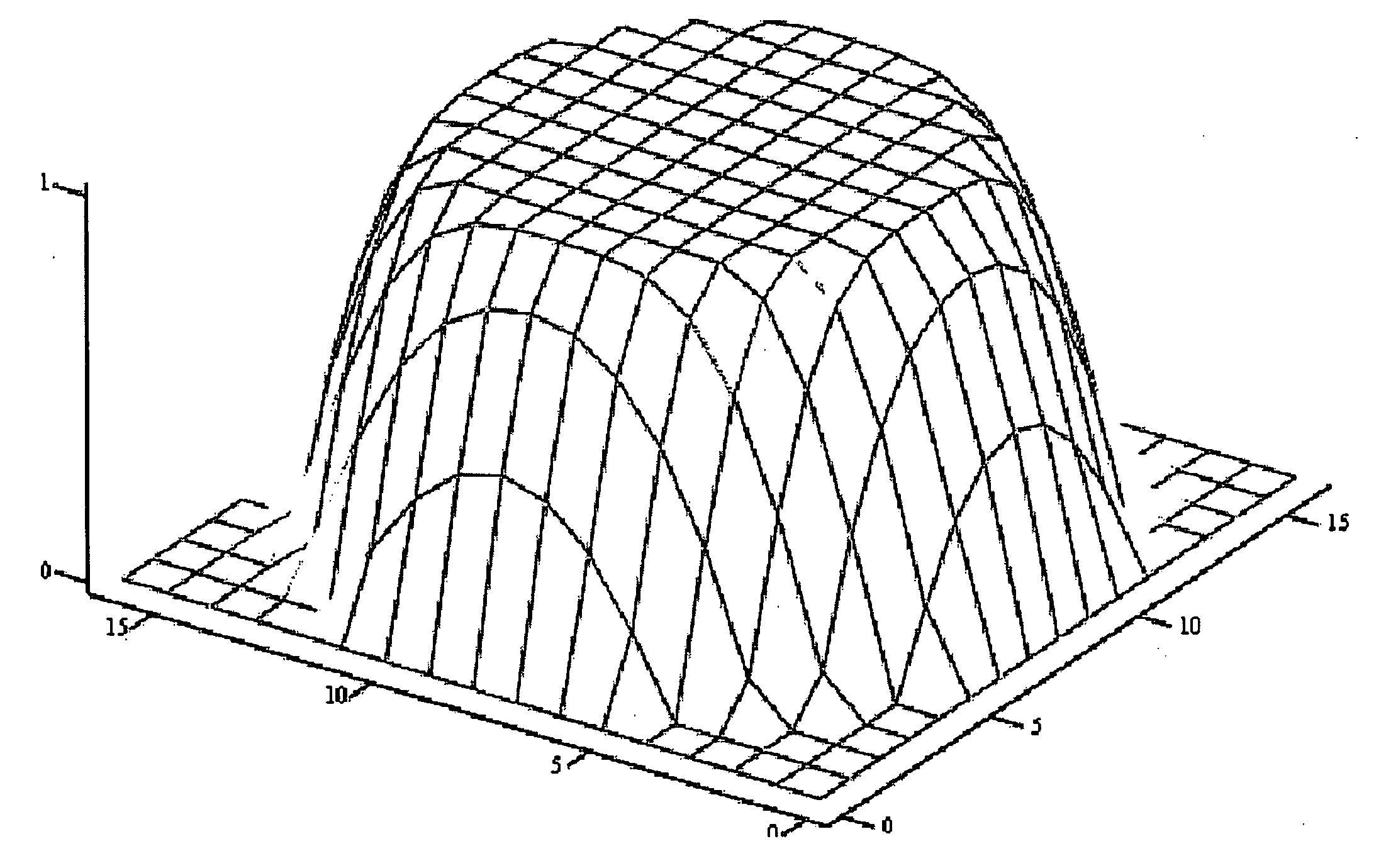
Surface Roughness Characterization

[0038] Surface roughness, Rz, can be expressed in microns by a 10-point average roughness in accordance with ISO-R468 of the International Organization for Standardization. Roughness measurements are made using a stylus-type profilometer (Surfcom 1500A manufactured by Tokyo Seimitsu Kabushiki Kaisha of Tokyo, Japan) as described in ASME B46.1 - 1995 using a trace length of 26 mm. ARp and ARt, and the area kurtosis are measured by tracing the roughness over a 5.6 mm×5.6 mm area in 201 steps using the Perthometer Concept system manufactured by Mahr GmbH, Gottingen, Germany.

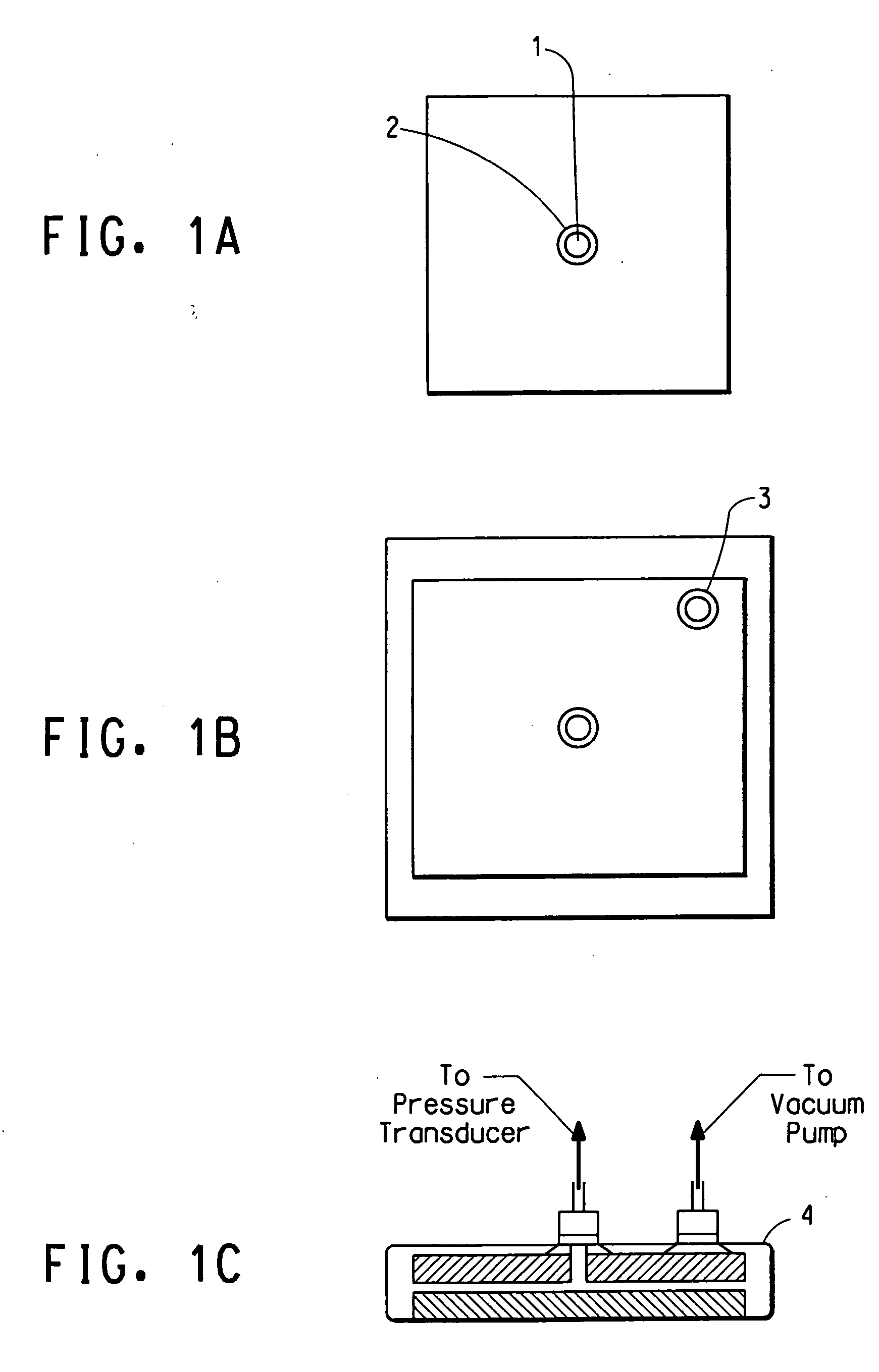
De-Airing Efficiency at Room Temperature

[0039] De-airing efficiency of an interlayer with a specified pattern is determined using an apparatus which allows the absolute pressure of the interstitial space in an assembly to be measured (FIG. 1). The interlayer to be tested is assembled as a normal assembly, except that the top plate of glass has a hole (1) drilled through its cen...

example 2

[0043] Various ionomer sheets having an methacrylic acid content of approximately 19% and a degree of neutralization of 37% with sodium ion were obtained in a size of 600-mm square at a thickness of about 2.3-mm were placed between two sheets of abrasion-resistant coated polycarbonate (Lexan® MR 3 / 16″ thickness). This sandwich was then vacuum-bagged using standard techniques and a vacuum was drawn on the assembly for 30 minutes at about 30 torr absolute pressure. After this deairing step, the vacuum-bagged assembly was then heated in a convection air oven to 120 C. for 45 minutes after which it was cooled back down to room temperature while under vacuum. This procedure was utilized to produce ionomer sheeting possessing low haze and smooth, essentially parallel surfaces. These materials were used as precursors for then embossing with textured rubber sheets as described previously, metal mesh and other materials were used to create a variety of roughened / textured surfaces to further ...

example 3

[0046] A DuPont Thermomechanical Analyzer was used to make delicate measurements of the degree of compression as a function of the applied force and parameters of time and temperature. Some of the ‘bulk’ flow properties are displayed in Table I where the displacement of the TMA probe was indexed at 20 and 60% of the respective thickness of the interlayer under study (PVB and lonomer). At each force level, the temperature was ramped at 5 C. / minute from −20 C. to 200 C. and the temperature was recorded when each of the compression indices was obtained.

TABLE 1Temperature (C.) for Probe to Reach 20%and 60% Compression of InterlayerWeightThicknesson ProbePressureTEMP. @ −60%TEMP. @ −20%(gms.)(psi)PVBIonomerPVBIonomer30.9151142134114154.4131114108975014.51131038991681198.158856480

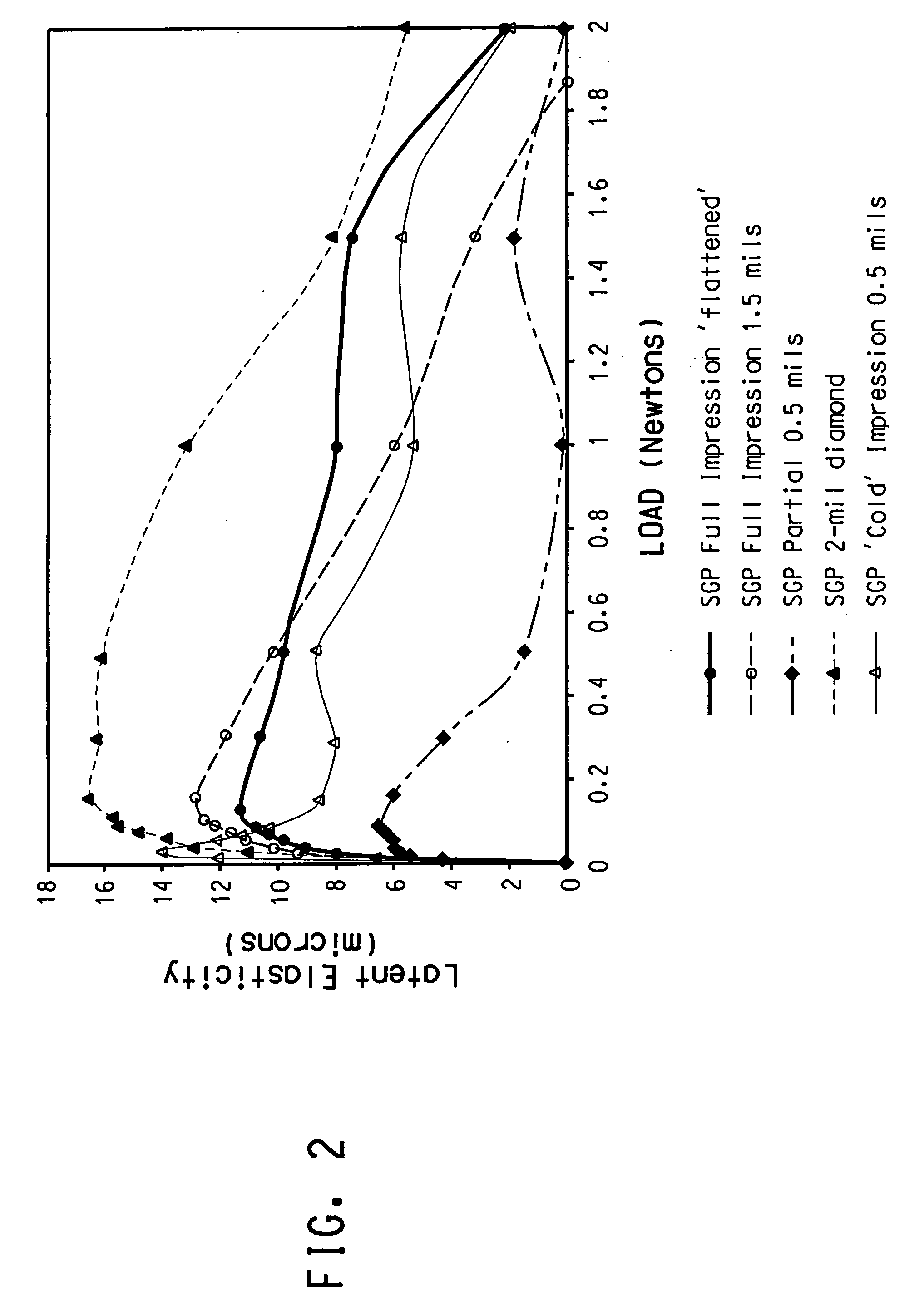
FIG. 3 is a diagram of the degree of elastic recovery which occurs after compressing the respective surface texture as a function of residual load. There exists a minimum amount of force (pressure) that is nece...


PUM

PropertyMeasurementUnit
widthaaaaaaaaaa
widthaaaaaaaaaa
widthaaaaaaaaaa

Abstract

This invention relates to thermoplastic interlayers for laminated safety glass with superior vacuum de-airing at elevated temperatures and superior tacking and edge sealing properties. The sheeting has surface pattern on at least one of the surfaces characterized by flat surfaces with substantially uninterrupted channels for airflow in at least two non-parallel directions. The channels allow for rapid de-airing while the area roughness parameter ratio ARp/ARt in the range of 0.52 to 0.62, ARt being less than 32 μm, and area kurtosis less than 2.5, allow for ease of tacking of the interlayer onto glass and edge sealing after de-airing has been completed. Said surface pattern may also be superimposed onto a pattern which is generated by melt fracture or other means on at least one side to enhance de-airing and aid edge sealing.

Description

BACKGROUND OF THE INVENTION [0001] This application is a Continuation-in-part of U.S. application Ser. No. 10 / 267,257, filed on Oct. 9, 2002, which is a Continuation-in-part of U.S. application Ser. No. 09 / 674,317, filed on May 12, 1999, now abandoned, which claimed the benefit of U.S. application Ser. No. 09 / 078,984, filed on May 14, 1998, now abandoned.[0002] In the fabrication of laminated safety glass, it is customary to place a piece of thermoplastic sheeting between two pieces of float glass. It is also common that the thermoplastic interlayer's surface can be roughened to avoid blocking, i.e., one layer of interlayer sticking to another. The roughness on the interlayer can also allow the interlayer to be moved while the two pieces of glass are aligned as the glass / interlayer / glass sandwich (hereinafter, “assembly”) is constructed. In constructing such an assembly, air is trapped in the interstitial space between the glass surface and the bulk of the thermoplastic interlayer. ...

Claims


Application Information

Patent Timeline
Patent Type & Authority Applications(United States)
IPC IPC(8): B32B17/06G11B5/64
CPCB29C59/022Y10T428/24612B29C2059/023B32B17/10036B32B17/10577B32B17/10743B32B17/10761B32B17/1077B32B17/10788B32B17/10862B32B17/10981Y10T428/24702Y10T428/24479Y10T428/24355B29C59/04Y10T428/31645Y10T428/31649
Inventor SMITH, CHARLES ANTHONYANDERSON, JERREL CHARLES
Owner PERFORMANCE MATERIALS NA INC
Why Eureka
Try Eureka