
Fuel cell coolers with inverse flow and condensation zone

Active Publication Date: 2006-06-29
HYAXIOM INC
View PDF29 Cites 12 Cited by
  • Summary
  • Abstract
  • Description
  • Claims
  • Application Information

AI Technical Summary

Benefits of technology

[0005] Objects of the invention include: providing for a high degree of liquid condensation in fuel cell stacks fueled by reformate containing carbon monoxide, without reducing cell performance as a result of carbon monoxide poisoning (CO); minimizing electrolyte loss in a phosphoric acid or high temperature polymer electrolyte membrane (HTPEM) fuel cell stack; maximizing the life of a phosphoric acid or HTPEM fuel cell stack; and achieving, in a phosphoric acid or HTPEM fuel cell, low temperatures required for condensing electrolyte which evaporates into the reactant gases, together with a higher temperature required to prevent CO poisoning of the anodes of the fuel cell stack.

Problems solved by technology

A competing problem in a phosphoric acid fuel cell stack is that the reformate fuel provided by a fuel processing system which converts various hydrocarbon fuels to hydrogen, such as a steam reforming fuel processor, contains between 0.3% and 1.0% carbon monoxide (CO), which is a poison to the anode catalyst and impedes the oxidation of hydrogen at the anode.

Method used


Image

  • Fuel cell coolers with inverse flow and condensation zone
  • Fuel cell coolers with inverse flow and condensation zone
  • Fuel cell coolers with inverse flow and condensation zone

Examples


Embodiment Construction

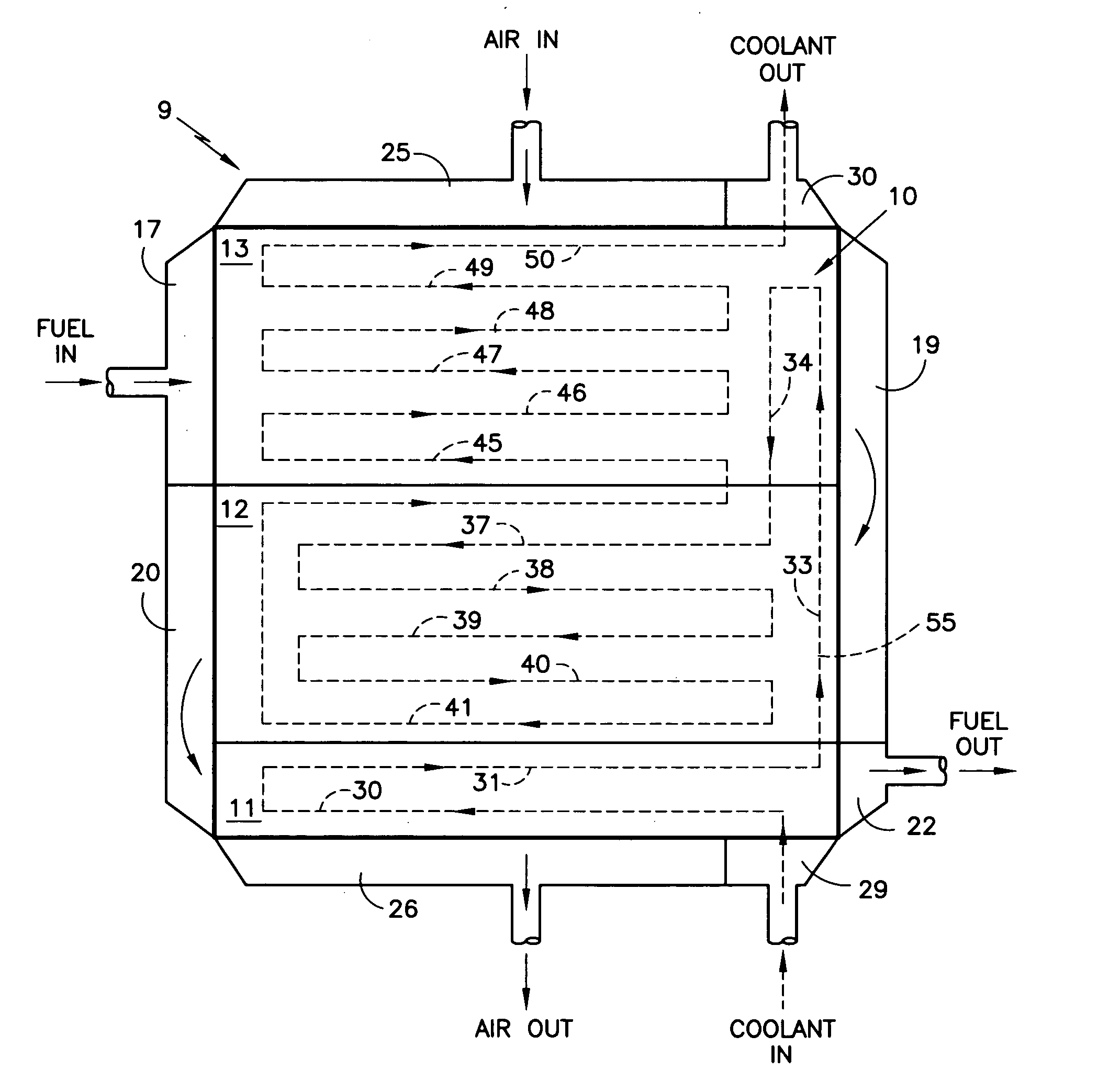
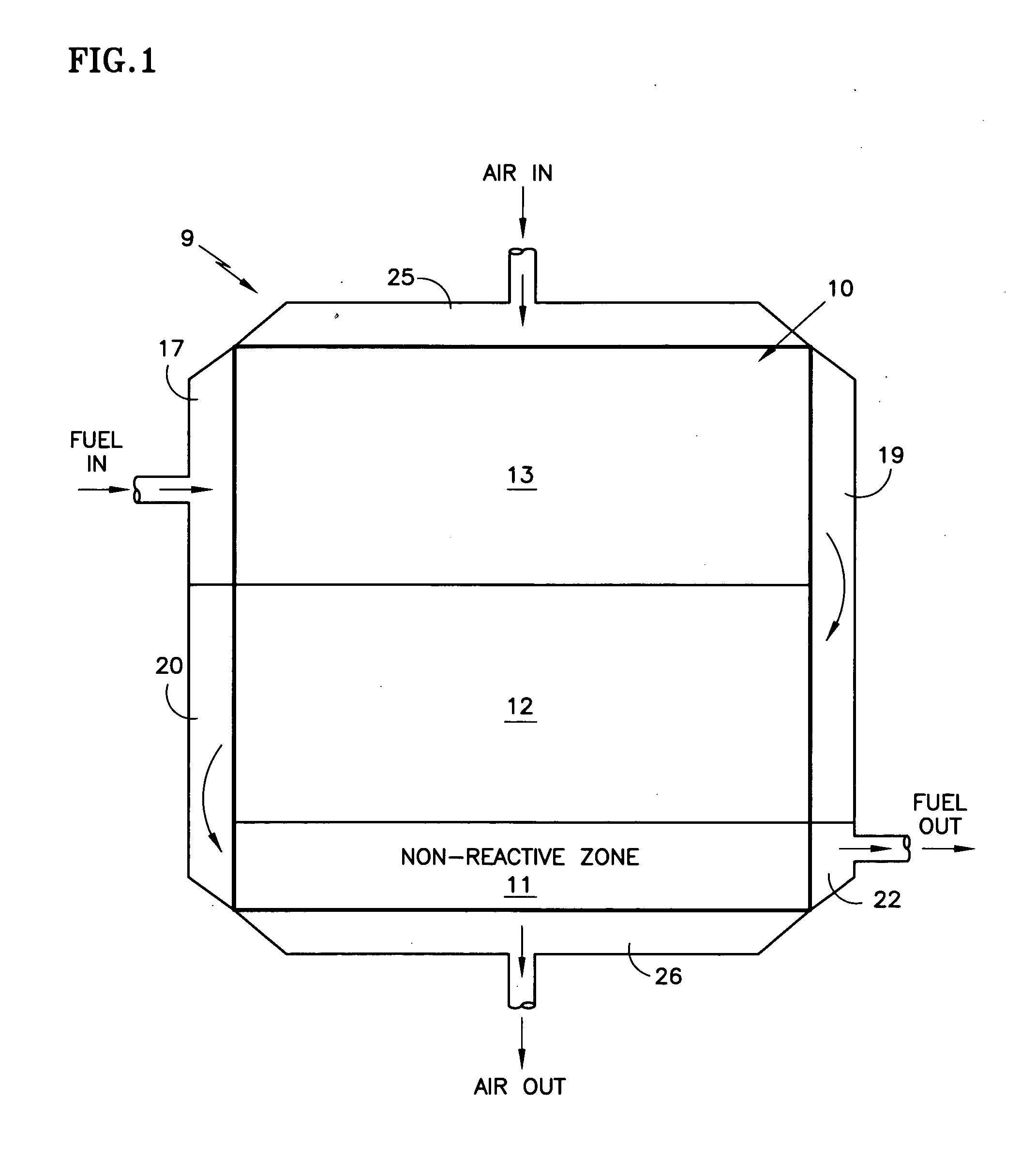
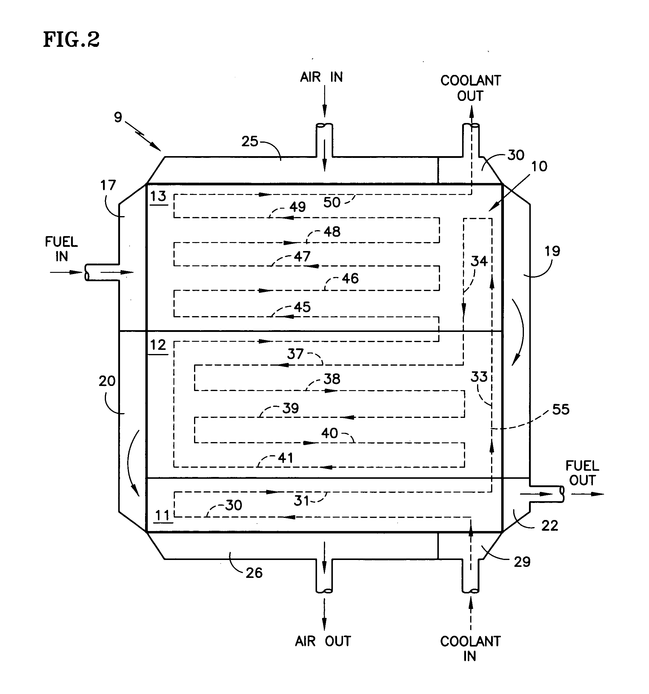
[0015] Referring to FIG. 1, a fuel cell stack 9, according to the invention, includes a plurality of fuel cells 10 having three zones 11-13. Each of the zones 11-13 generally overlaps one of three fuel flow passes in the fuel flow channels. Fuel enters through a fuel inlet manifold 17, and flows to the right (as seen in FIG. 1) through the fuel flow fields associated with the third zones 13. Then the fuel flows through a turnaround manifold 19 and then to the left (as seen in FIG. 1) through the fuel flow fields associated with the second zones 12, to a second turnaround manifold 20, and then to the right (as seen in FIG. 1) through the flow fields associated with the first, non-reactive zones 11, and outwardly through a fuel exit manifold 22.

[0016] The first zones 11 are non-reactive because the portion of each fuel cell comparable with the first zones 11 do not have a cathode catalyst and therefore do not react with the reactant gases.

[0017] In the embodiment herein, the oxidant...


PUM


Abstract

A fuel cell system having a fuel cell stack (9) employing a phosphoric acid or other electrolyte, includes a non-reactive zone (11) in each of a group of fuel cells between corresponding coolant plates (55), the coolant entering the coolant plates in an area adjacent to the non-reactive zones (29-31). Each fuel cell has three-pass fuel flow fields, the first pass substantially adjacent to a third zone (13), remote from the first zone, the second pass substantially adjacent to a second zone contiguous with the first zone, the coolant flowing (33, 34) from a coolant inlet (29) through the first zone, to the far side of the second zone, and (37-41) from the near side of the second zone to the third zone and thence (45-50) to a coolant exit manifold (30), which assures temperatures above 150° C. (300° F.), to mitigate CO poisoning of the anode within the reactive zones, and assuring temperatures below 140° C. (280° F.) to promote sufficient condensation of evaporated electrolyte in the non-reactive zones, so as to provide a long system life.

Description

TECHNICAL FIELD [0001] This invention relates to a fuel cell power plant system which converts fuel to useable heat and electric power, employing a fuel cell stack which has fuel flow field and cooler planforms that promote a high degree of electrolyte condensation (which may be phosphoric acid in a fuel cell stack employing a phosphoric acid electrolyte, or may be a free acid electrolyte in a high temperature polymer electrolyte membrane (HTPEM) fuel cell stack) while maintaining a sufficiently high reaction temperature to mitigate CO poisoning of the catalysts. BACKGROUND ART [0002] In a known fuel cell system employing phosphoric acid electrolyte, cooler plates interposed between groups of fuel cells have a simple serpentine cooler flow path and utilize water coolant. Liquid water enters the cooler plates and a two-phase, water / steam mixture exits the cooler plates. A small fraction of the heat removal is due to increasing the sensible heat of the water as it increases to its boi...

Claims


Application Information

Patent Timeline
IPC IPC(8): H01M8/04
CPCH01M8/0258H01M8/0263H01M8/0267H01M8/04074H01M8/04276H01M8/086H01M2008/1095Y02E60/50H01M8/2425H01M8/04H01M8/241
Inventor FREDLEY, ROBERT R.NITTA, BHIMASHANKAR V.
Owner HYAXIOM INC
Learn More