Capillary perfused bioreactors with multiple chambers

Inactive Publication Date: 2006-06-29
VANDERBILT UNIV
View PDF16 Cites 23 Cited by
  • Summary
  • Abstract
  • Description
  • Claims
  • Application Information

AI Technical Summary

Benefits of technology

[0040] The bioreactor further includes one or more supporting members positioned outside the confined region of the chamber for supporting the second substrate. Additionally, the bioreactor further includes at least one supporting member positioned inside the confined region of the chamber for supporting the second substrate. Note that the chamber is formed

Problems solved by technology

For instance, it has been known that liquid-gas interface created in some models of reactors is particularly damaging for mammalian cells.
While these systems imply a low effort for process control, the productivity is low compared to that in perfused systems, the third mode, where a permanent inflow of substrate and outflow of medium takes place.
One of the limitations when developing large three-dimensional tissues is the lack of a proper vascular supply for nutrient and metabolite transport.
However, they cannot resist significant compressional forces.
Were the pressures in the capillaries as high as those in the arterioles, the capillary wall thickness would be too great to allow these critical transport phenomena.
It is this intercalation process that is so difficult to replicate with microfabrication.
Each of these approaches has limitations, including the inability to have sustained and controlled chemotactic gradients (all systems), the inability to visualize migration in real time or with physiologic shear stress (Boy

Method used


Image

  • Capillary perfused bioreactors with multiple chambers
  • Capillary perfused bioreactors with multiple chambers
  • Capillary perfused bioreactors with multiple chambers

Examples


examples

Capillary Bioreactor

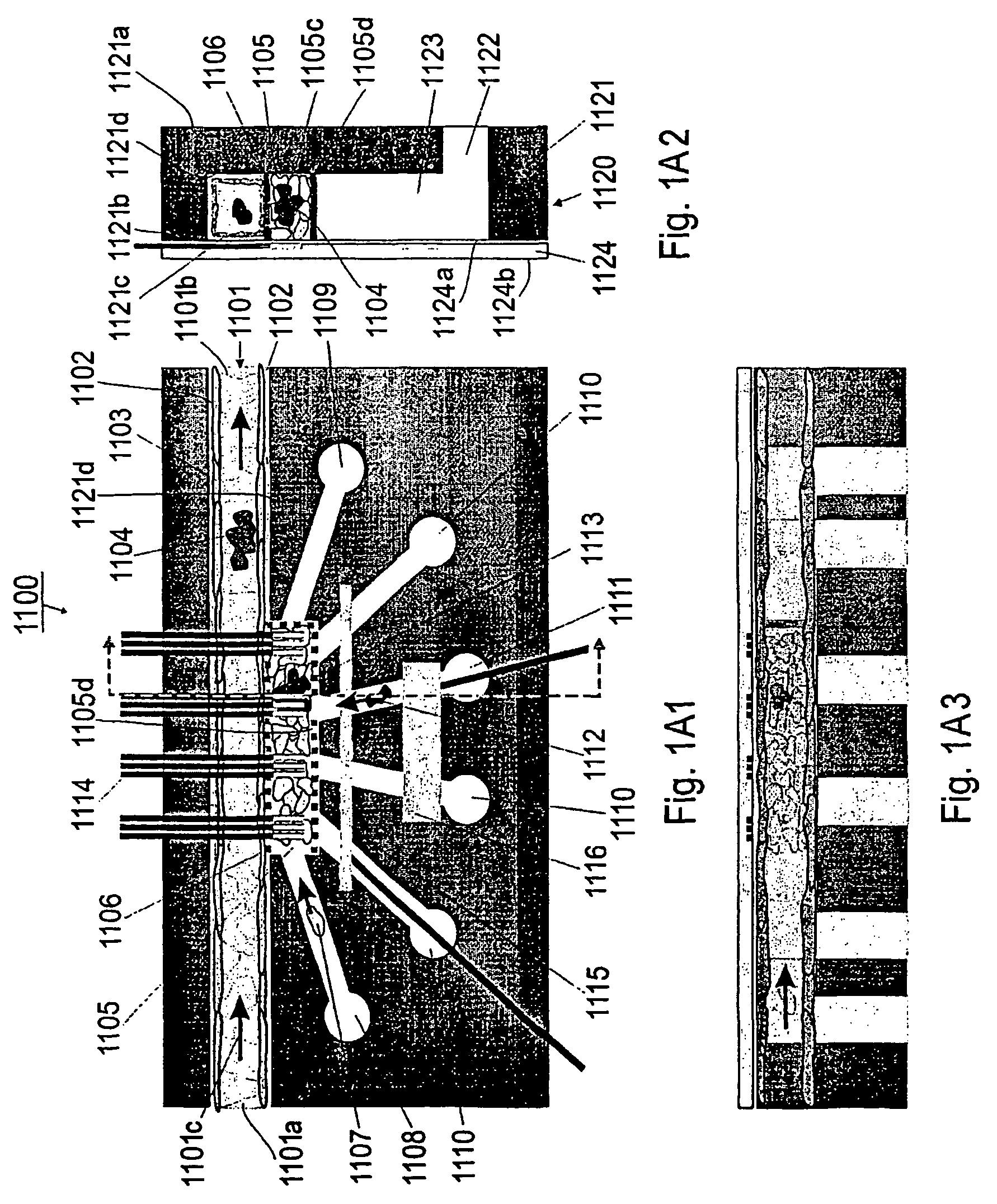
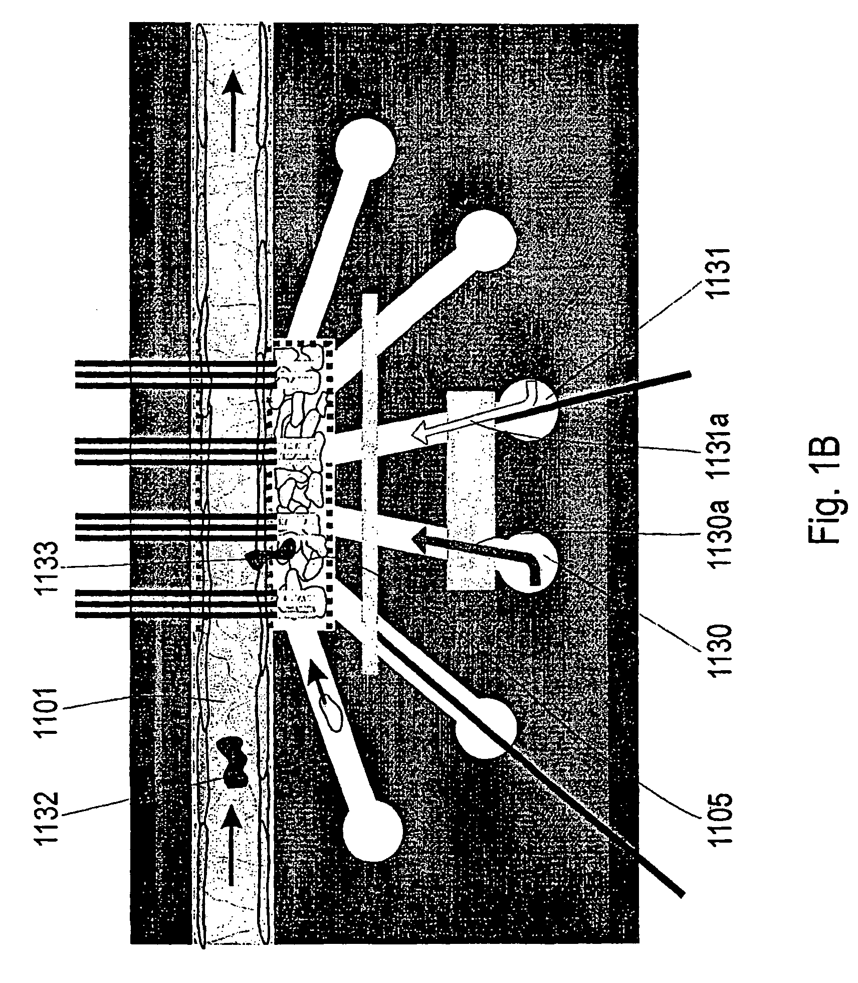
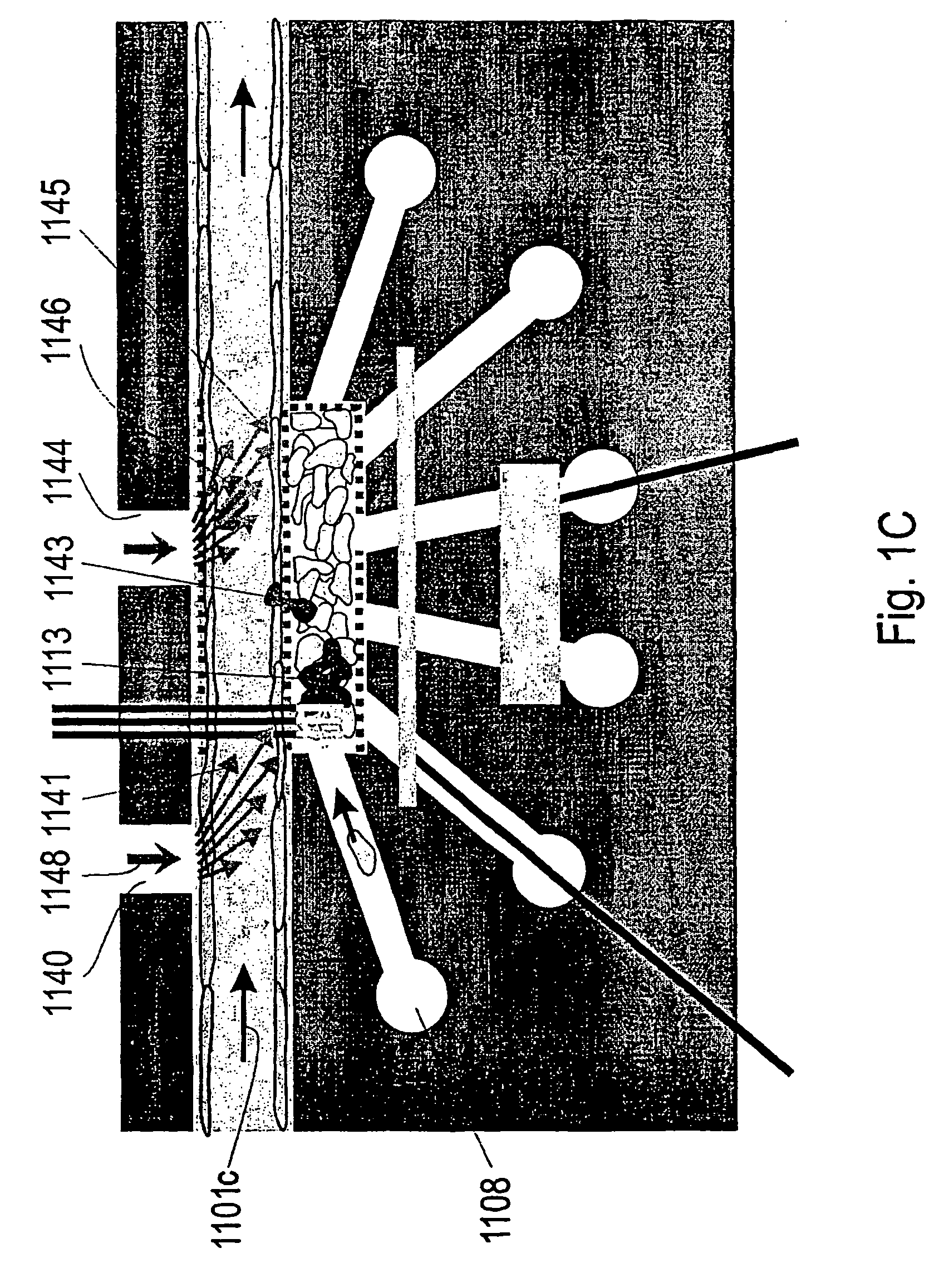
[0087] Referring now to FIGS. 1(A-D), the present invention can be practiced in association with an inventive bioreactor 1100 and its variants as shown in FIGS. 1(A-D). In one embodiment, referring first to FIGS. 1A1, 1A2 and 1A3, the bioreactor 1100 includes a first substrate 1124 having a first surface 1124a, an opposite second surface 1124b and edges. The bioreactor 1100 further includes a second substrate 1121 having a first surface 1121a and an opposite second surface 1121b, defining a cavity 1121c with a bottom surface 1121d, where the bottom surface 1121d is located therebetween the first surface 1121a and the second surface 1121b. The first surface 1124a of the first substrate 1124 is received by the second surface 1121b of the second substrate 1121 to cover the cavity 1121c so as to form a channel 1101 for receiving cells and a liquid medium. The second substrate 1121 can be fabricated from glass, Mylar, PDMS, silicon, a polymer, a semiconductor, or any...


PUM


Abstract

A bioreactor for cultivating living cells in a liquid medium. In one embodiment of the present invention, the bioreactor includes a first substrate having a first surface, an opposite second surface and edges. The bioreactor further includes a second substrate having a first surface and an opposite second surface, defining a cavity with a bottom surface, where the bottom surface is located therebetween the first surface and the second surface. The first surface of the first substrate is received by the second surface of the second substrate to cover the cavity so as to form a channel for receiving cells and a liquid medium. In forming the bioreactor, the channel is sized to allow the growth of a layer of cells on a biocompatible coating layer and a flow of liquid in the channel. The flow of liquid is controlled so as to provide a known shear force to the layer of cells. The flow of liquid can be further controlled so as to provide an environment that simulates a vascular space in the channel.

Description

[0001] The present invention was made with Government support under Grant No. N66001-01-C-8064 awarded by the Defense Advanced Research Projects Administration and the Office of Naval Research. The present invention was also made with Government support under Grant 5R43 RR016124-02 awarded by the National Institute of Health. The United States Government may have certain rights to this invention pursuant to these grants.[0002] This application is being filed as a PCT International Patent Application in the name of Vanderbilt University, a U.S. national corporation, applicant for the designation of all countries except the US, and John P. Wikswo, Franz J. Baudenbacher, Ales Prokop, and Eugene LeBoeuf, all U.S. nationals and residents, applicants for the designation of the US only, on 27 Aug. 2003. [0003] Some references, which may include patents, patent applications and various publications, are cited in a reference list and discussed in the description of this invention. The citati...

Claims


Application Information

Patent Timeline
IPC IPC(8): C12M1/34
CPCB01L3/502746B01L3/502761B01L2200/0668B01L2300/0816B01L2300/0864C12M29/10B01L2300/10B01L2400/0406B01L2400/0415B01L2400/0487C12M23/16B01L2300/0877
Inventor WIKSWO, JOHN P.BAUDENBACHER, FRANZ J.PROKOP, ALEXLEBOEUF, EUGENE J.CHUNG, CHANG Y.CLIFFEL, DAVIDHASELTON, FREDERICK R.HOFMEISTER, WILLIAM H.LIN, CHARLES P.MCCAWLEY, LISA J.REISERER, RANDALL S.STREMLER, MARK A.
Owner VANDERBILT UNIV
Why Eureka
Try Eureka