Modular total ankle prosthesis apparatuses, systems and methods, and systems and methods for bone resection and prosthetic implantation

a total ankle and prosthesis technology, applied in the field of orthopaedic prostheses, can solve the problems of affecting the treatment effect the concept of total ankle arthroplasty has a long and relatively unsuccessful history, and the replacement of an ankle joint can be particularly problematic, etc., to achieve the effect of improving the quality of li

Inactive Publication Date: 2006-06-29
INTEGRA LIFESCI
View PDF76 Cites 163 Cited by
  • Summary
  • Abstract
  • Description
  • Claims
  • Application Information

AI Technical Summary

Benefits of technology

[0011] Methods and systems to prepare a bone surface for implantation of a prosthesis can include determining a location for a curved cut line on the bone surface and drilling a series of holes tangent to the curved cut line to create a curved bone resection surface. Methods and systems for the implantation of an ankle prosthesis can include the use of an alignment guide, tibia and talus drill guides, tibia and talus saw guides, and tibia and talus broach guides, all components that can be placed on and removed from a plurality of alignment anchor pins throughout the implantation procedure. A method for medially to laterally implanting an ankle joint prosthesis can include exposing tibia and talus bones from the medial side, resection of the tibia and talus bones, broaching the tibia and talus bones, and positioning and affixing the ankle joint prosthesis components.

Problems solved by technology

The concept of total ankle arthroplasty has a long and relatively unsuccessful history.
Replacement of an ankle joint can be particularly problematic due to the relatively small articular surfaces, complex biomechanics, limited access to the joint during replacement, and wide variation in patient candidacy.
These factors have led to post-operative complications such as loosening, subsidence, pain, and prosthetic wear.
In addition to these technical difficulties, regulatory agencies have classified ankle prosthetics in a manner substantially limiting scientific progress in ankle replacement due to the financial burden of obtaining market clearance for such devices.
Rotations in the frontal region are usually not well supported as there is little curvature in this region.
These motions can occur actively and lead to edge loading, causing higher stress and greater propensity for wear.
Also, as the articular surfaces can be designed for mismatch, even under optimum implant positioning and loading, higher stress will be seen at the contact point due to the point loading associated with mismatched radii of the articular surfaces.
These methods of bone resection have several disadvantages including over-cutting of the resection of the bone surfaces, initial misalignment of the cut, and performing cuts that are not straight throughout the length of the cut.
These disadvantages can lead to longer healing time or more pain for the patient or performance problems of the prosthesis due to misalignment or improper contact between the implant components and the resected bone surfaces.

Method used


Image

  • Modular total ankle prosthesis apparatuses, systems and methods, and systems and methods for bone resection and prosthetic implantation
  • Modular total ankle prosthesis apparatuses, systems and methods, and systems and methods for bone resection and prosthetic implantation
  • Modular total ankle prosthesis apparatuses, systems and methods, and systems and methods for bone resection and prosthetic implantation

Examples


Embodiment Construction

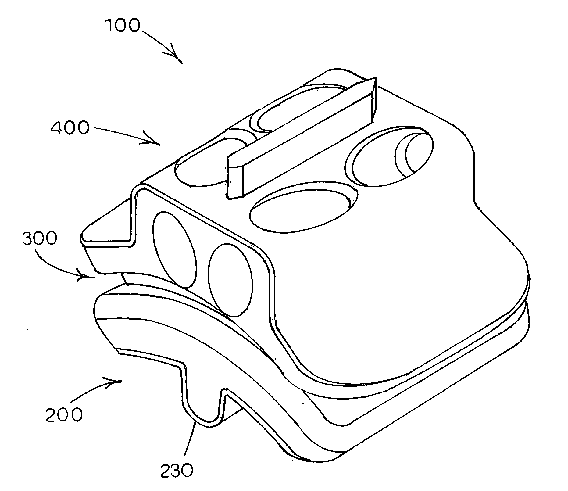
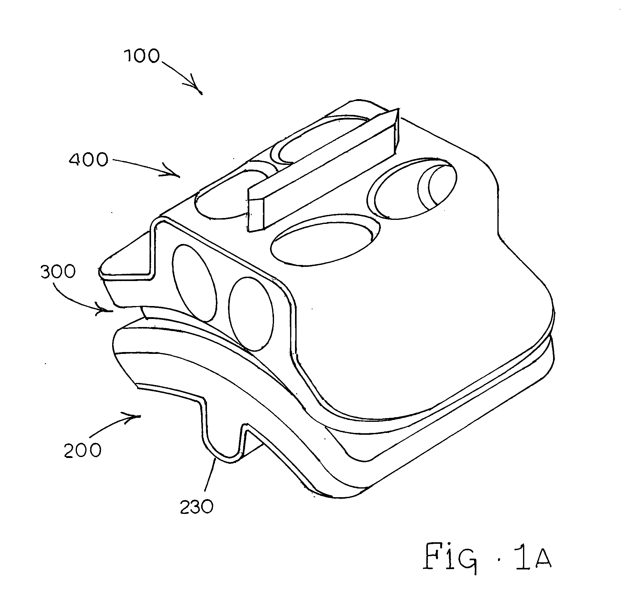
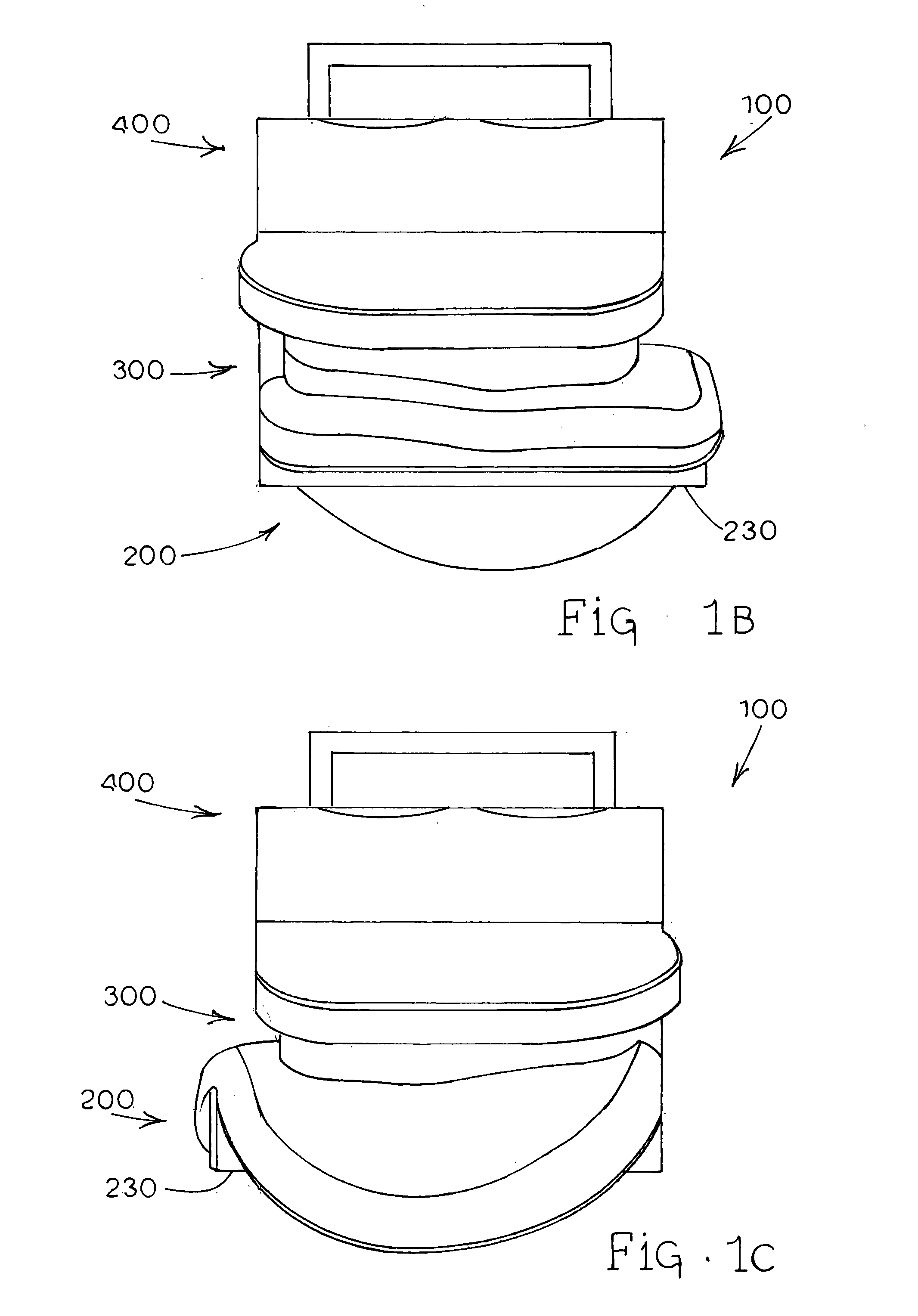
[0065] In accordance with the present disclosure, ankle prosthesis apparatuses, systems and methods are provided. Additionally, systems and methods for bone resection and implantation of prosthetics are provided, including surgical techniques and related instrumentation.

[0066] Referring to FIGS. 1A-1H of the drawings, various views of an assembled ankle prosthesis apparatus generally designated 100 are provided. Referring specifically to FIG. 1A of the drawings, a top perspective view of an embodiment of ankle prosthesis apparatus 100 is illustrated. As shown, ankle prosthesis 100 comprises a lower talar component generally designated 200, a bearing component generally designated 300 positioned above and against talar component 200, and an upper tibial component generally designated 400 positioned above and against bearing component 300. FIG. 1B of the drawings provides an anterior view of ankle apparatus 100, and FIG. 1C of the drawings provides a posterior view of ankle apparatus...


PUM


Abstract

Ankle prosthesis apparatuses, systems and methods are provided as disclosed herein. Additionally, systems and methods for bone resection and implantation of prosthetics are provided, including surgical techniques and related instrumentation. An ankle prosthesis apparatus can include a talar component having a lower surface with a bone fixation portion for fixation to a talus bone and an upper surface designed for articulation with a bearing component. The bearing component can have a lower surface for articulation with the talar component and an upper surface for articulation with a tibial component. The tibial component can have a lower surface for articulation with the bearing component and an upper surface with a bone fixation portion for fixation to a tibia bone and/or a fibula bone. The bearing component can have a protrusion on its upper surface adapted for engagement with a recess on the tibial component to allow desired rotational and translational movement. Methods and systems can be used to prepare a bone surface for implantation of a prosthesis including determining a location for a curved cut line on the bone surface and drilling a series of holes tangent to the curved cut line to create a curved bone resection surface. Methods and systems can be used for the implantation of an ankle joint prosthesis including the use of an alignment guide, tibia and talus drill guides, tibia and talus saw guides, and tibia and talus broach guides, all components of which can be placed on and removed from a plurality of alignment anchor pins throughout the implantation procedure. A method for medially to laterally implanting an ankle joint prosthesis can include exposing tibia and talus bones from the medial side, resection of the tibia and talus bones, broaching the tibia and talus bones, and positioning and affixing the ankle joint prosthesis components.

Description

RELATED APPLICATION [0001] This application claims the benefit of U.S. Provisional Patent Application Ser. No. 60 / 602,786, entitled Modular Total Ankle Prothesis Apparatuses and Methods, filed Aug. 19, 2004, the disclosure of which is incorporated herein by reference in its entirety.TECHNICAL FIELD [0002] The present subject matter is directed generally to orthopedic prostheses. More specifically, the present subject matter is directed to ankle prosthesis apparatuses, systems and methods, and to systems and methods for bone resection and implantation of prosthesis apparatuses. BACKGROUND ART [0003] The concept of total ankle arthroplasty has a long and relatively unsuccessful history. Only recently has total ankle arthroplasty regained some recognition as a viable treatment for limited indications. Replacement of an ankle joint can be particularly problematic due to the relatively small articular surfaces, complex biomechanics, limited access to the joint during replacement, and wid...

Claims


Application Information

Patent Timeline
Patent Type & Authority Applications(United States)
IPC IPC(8): A61F2/42A61B17/17A61B17/90
CPCA61B17/14A61B17/15A61F2/4202A61F2/4606A61F2/4684A61F2002/30878A61F2002/4205A61F2002/4207A61B17/148A61B2017/1775A61B17/142A61B17/1775
Inventor ROBINSON, SHAWNFOLEY, MARK RAYBALL, ROBERT J.BRAGE, MICHAELGILL, LOWELL HARLEYDIGIOVANNI, CHRISTOPHER WILLIAM
Owner INTEGRA LIFESCI
Why Eureka
Try Eureka