
Apparatus for producing hydrogen gas and fuel cell system using the same

a fuel cell and apparatus technology, applied in electrochemical generators, hydrogen separation using solid contact, sustainable manufacturing/processing, etc., can solve the problems of generating relative large amounts of co and it is practically difficult to eliminate the need for external heating means

Inactive Publication Date: 2006-07-06
DAIKIN IND LTD
View PDF8 Cites 14 Cited by
  • Summary
  • Abstract
  • Description
  • Claims
  • Application Information

AI Technical Summary

Benefits of technology

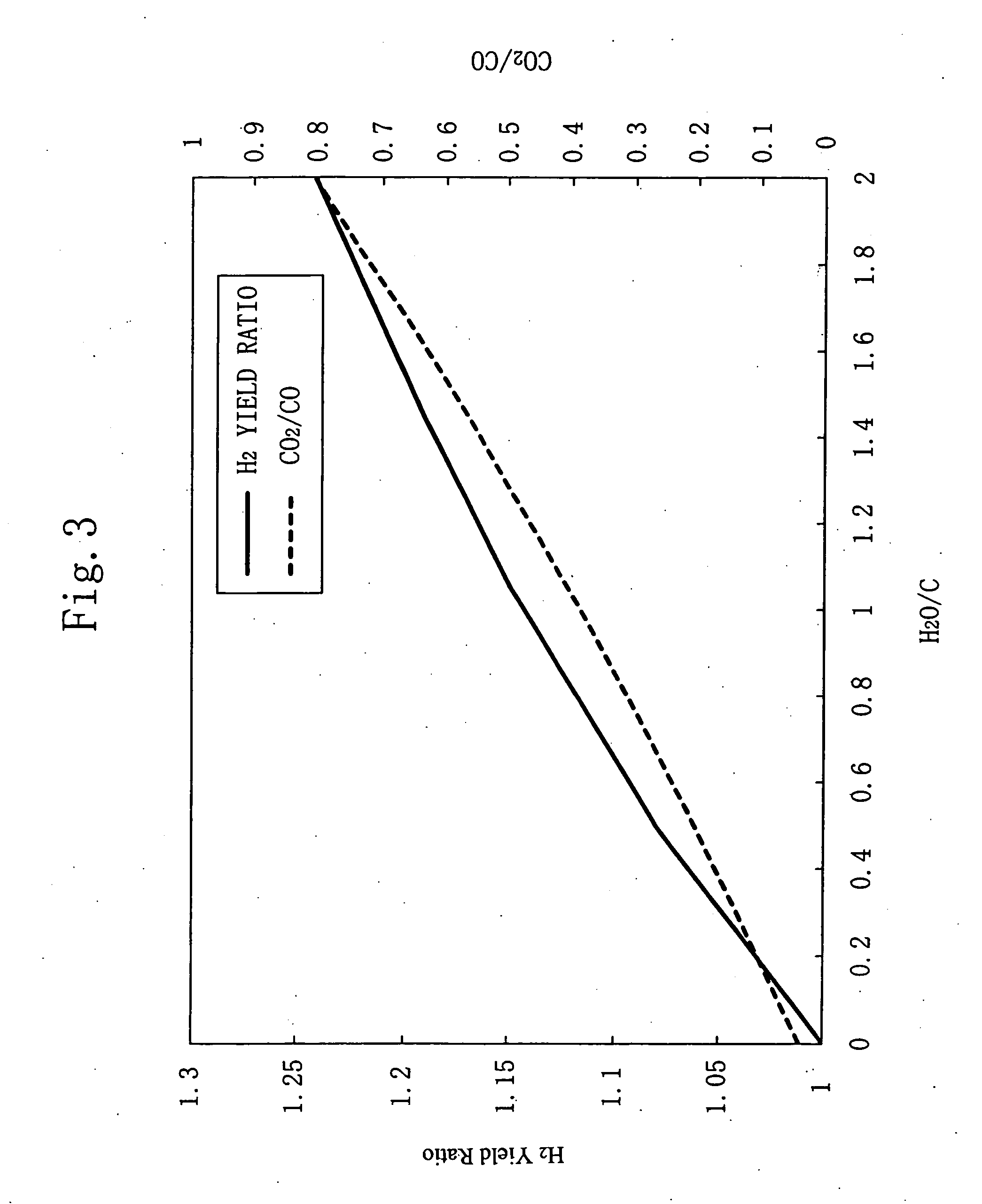
[0019] The reaction formula (1) is a partial oxidation reaction by which target hydrogen is obtained and CO, which is produced simultaneously with the hydrogen, is oxidized by the water gas shift reaction expressed by the reaction formula (2), during which hydrogen is generated. The addition of steam to the source gas does not much affect the fuel conversion rate in the partial oxidation reaction of the reaction formula (1), but the steam addition makes it easy for the water gas shift reaction of the reaction formula (2) to take place (because the equilibrium inclines toward the generation side), thereby increasing the yield of hydrogen.
[0045] That is, the coefficient of fuel (hydrogen) utilization and the coefficient of oxygen (air) utilization in a fuel cell vary with the load (the amount of electric power used) of the fuel cell. In other words, when the amount of fuel flowing into the fuel cell and the amount of oxygen flowing into the fuel cell are fixed, if the output current value of the cell is varied, the amounts of hydrogen and oxygen that are consumed in the cell reaction vary. This is accompanied with a change in the amount of steam. Accordingly, by controlling the output current value, it becomes possible to supply to the fuel reformer (5) a discharged gas with a given oxygen concentration and a given steam concentration that are suitable for the reforming of fuel.

Problems solved by technology

Moreover, relatively large amounts of CO are generated by the hydrocarbon partial oxidation reaction and the steam reforming reaction.
Accordingly, it is practically difficult to eliminate the need for an external heating means by just employing the concept that steam is added for the purpose of mainly causing a steam reforming reaction to take place.

Method used


Image

  • Apparatus for producing hydrogen gas and fuel cell system using the same
  • Apparatus for producing hydrogen gas and fuel cell system using the same
  • Apparatus for producing hydrogen gas and fuel cell system using the same

Examples


Embodiment Construction

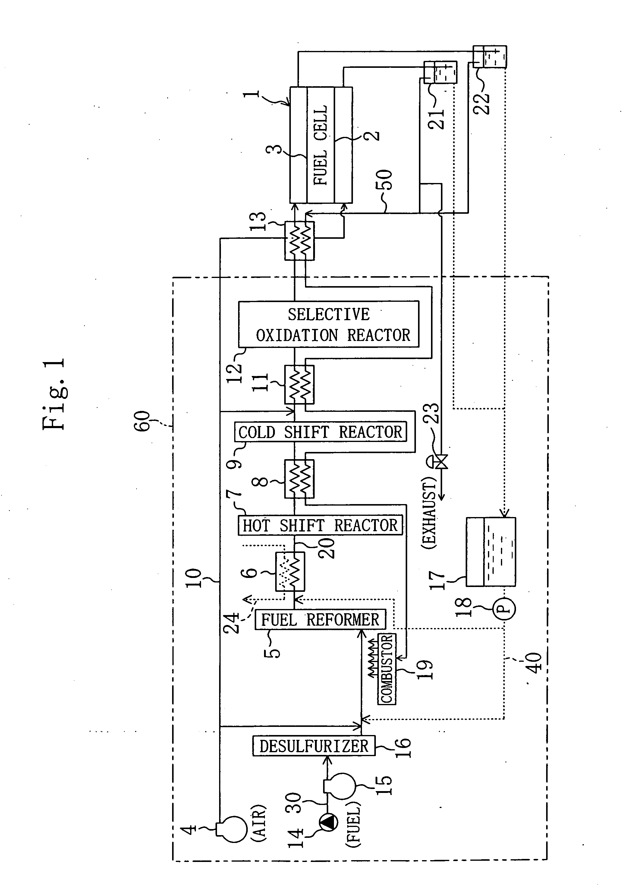
[0055] In order to describe the present invention in detail, the description thereof will be made by making reference to the accompanying drawings. The following are main reference numerals in the drawings.

[0056]1: FUEL CELL

[0057]2: OXYGEN ELECTRODE

[0058]3: HYDROGEN ELECTRODE

[0059]4: AIR COMPRESSOR (AIR SUPPLY)

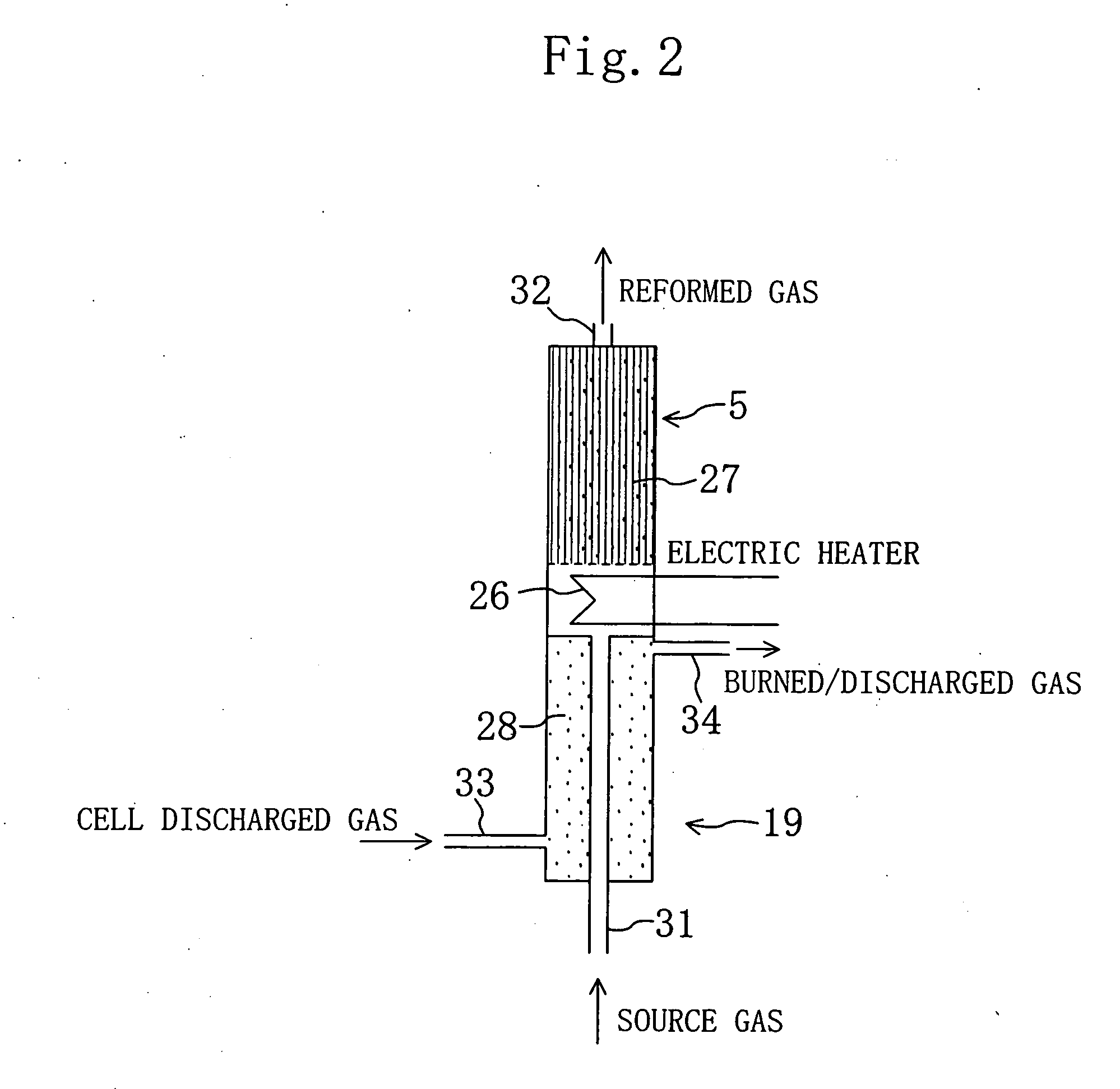
[0060]5: FUEL REFORMER

[0061]7: CO HOT SHIFT REACTOR

[0062]14: WATER TANK (STEAM SUPPLY)

[0063]27: CATALYST

[0064]35: DISCHARGED GAS SUPPLY PIPE (DISCHARGED GAS SUPPLY MEANS)

[0065]38: POWER CONTROLLER (OUTPUT CURRENT CONTROL MEANS)

[0066]39: FLOW RATE CONTROL VALVE (AIR SUPPLY MEANS)

[0067]40: WATER SUPPLY PIPE (STEAM SUPPLY MEANS)

[0068]60: HYDROGEN GAS GENERATOR

[0069] First, the entire fuel cell system will be described below.

[0070]FIG. 1 shows a configuration of the fuel cell system of the present invention, in which the reference numeral 1 denotes a fuel cell of the solid polyelectrolyte type having an oxygen electrode (cathode) 2 which is a catalyst electrode and ...


PUM


Abstract

Placed in a fuel reformer (5) is a catalyst (27) which exhibits an activity to the partial oxidation reaction of a source fuel. The source fuel, oxygen, and steam are supplied to the fuel reformer (5) such that the ratio O2 / C, i.e., the ratio of the number of moles of the oxygen to the number of moles of carbon of the source fuel, is not less than 0.9 times the O2 / C theoretical mixture ratio in the partial oxidation reaction, and the H2O / C ratio, i.e., the ratio of the number of moles of the steam to the number of the source fuel carbon moles is not less than 0.5, wherein the partial oxidation reaction occurs in the catalyst (27) to cause a water gas shift reaction to take place in which CO produced by the partial oxidation reaction is a reactant, for generation of hydrogen.

Description

TECHNICAL FIELD [0001] The present invention relates to a hydrogen gas generator for producing a hydrogen gas from a source fuel of the hydrocarbon family, oxygen, and steam and to a fuel cell system employing such a hydrogen gas, generator. BACKGROUND ART [0002] It is possible to generate hydrogen by the reforming of hydrocarbon or methanol, and hydrogen gas generators capable of hydrogen generation by such reforming are applicable to fuel cells, hydrogen engines, and the like. Fuel cells are known generally as an electricity generator in which hydrogen delivered as a fuel to the negative electrode and oxygen delivered as an oxidant to the positive electrode react together through an electrolyte. [0003] Japanese Patent Gazette No. S58-57361 shows a technique in which either air, air / oxygen, or air / steam is acted on hydrocarbon in the presence of a rhodium catalyst for obtaining hydrogen and CO (carbon monoxide) by partial oxidation. The reaction temperature is from 690 to −900 degr...

Claims


Application Information

Patent Timeline
IPC IPC(8): B01J7/00B01J8/02B01J8/04B01J19/24C01B3/48C01B3/58H01M8/06
CPCB01J8/0285B01J8/0453B01J19/2485B01J2208/00415B01J2208/00628C01B3/48C01B3/583C01B2203/0261C01B2203/0288C01B2203/044C01B2203/047C01B2203/066C01B2203/0811C01B2203/0822C01B2203/0827C01B2203/085C01B2203/0883C01B2203/1011C01B2203/1023C01B2203/1041C01B2203/1047C01B2203/1052C01B2203/1064C01B2203/1076C01B2203/1082C01B2203/1241C01B2203/1247C01B2203/127C01B2203/1604C01B2203/1614C01B2203/1685C01B2203/169C01B2203/82H01M8/0612Y02E60/50Y02P20/10B01J8/02H01M8/06
Inventor MATSUI, NOBUKIIKEGAMI, SHUJIOKAMOTO, YASUNORIYONEMOTO, KAZUO
Owner DAIKIN IND LTD
Learn More