Photon spacecraft

a spacecraft and photon technology, applied in the field of spacecraft propulsion system, can solve the problems of sudden disappearance of charge and complicated actual physics, and achieve the effect of reducing the effective mass of the hull

Inactive Publication Date: 2006-07-06
ST CLAIR JOHN QUINCY
View PDF0 Cites 2 Cited by
  • Summary
  • Abstract
  • Description
  • Claims
  • Application Information

AI Technical Summary

Benefits of technology

[0022] The gravitational potential between hyperspace and space is positive because the hyperspace energy is more positive than the negative energy around the hull. Thus the low-density, low-speed-of-light hyperspace energy flows through the wormhole and fills the hull. This has the effect of reducing the effective mas

Problems solved by technology

The actual physics is more complicated still because the electrons find that the resistance of hyperspace is lower

Method used


Image

  • Photon spacecraft
  • Photon spacecraft
  • Photon spacecraft

Examples


Embodiment Construction

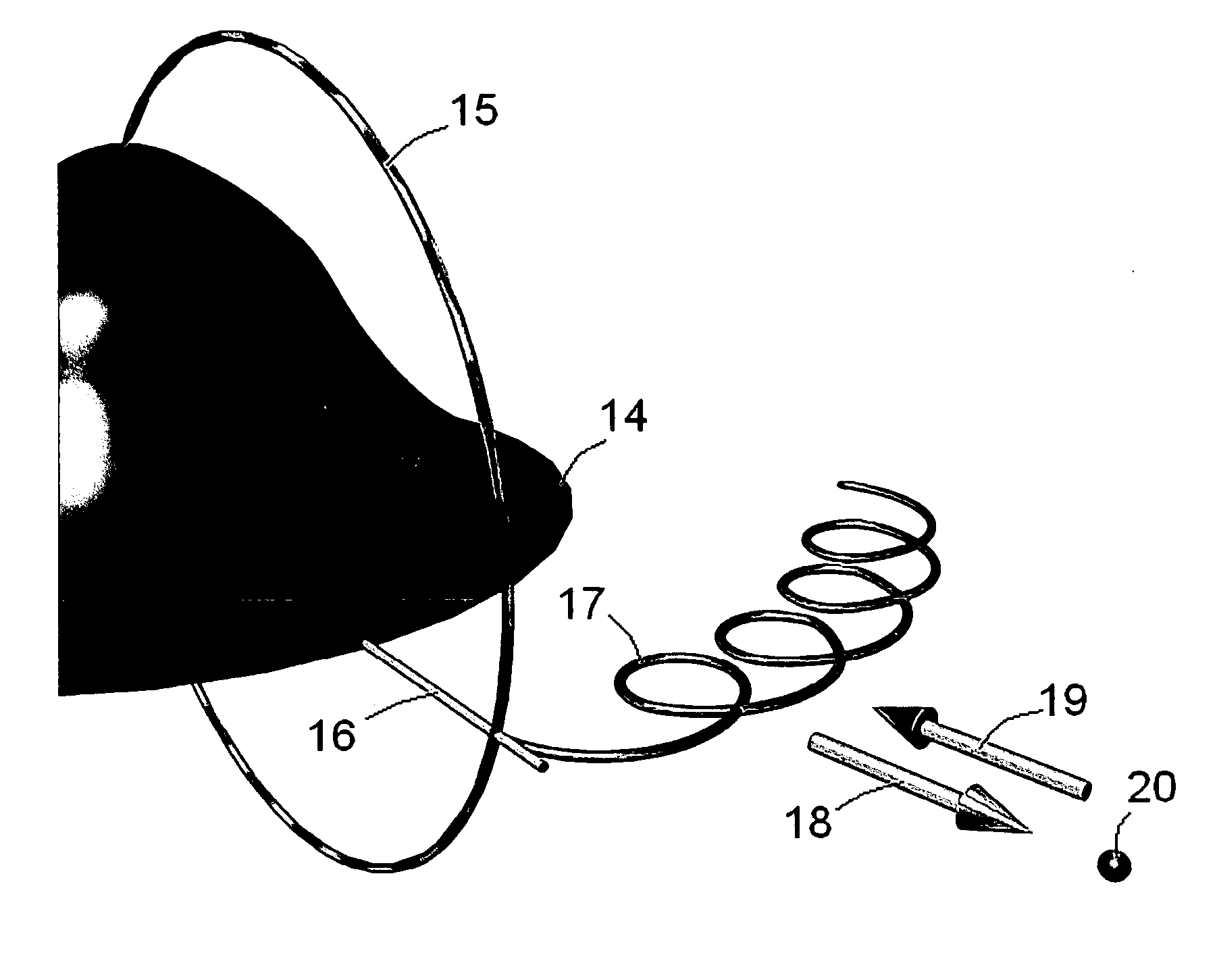
[0032] 1. The hull is made from a single sheet of aluminum which has been stretched to its yield point by hydraulic cylinders. An upper and lower die is CNC machined to the profile of the hull. The soft sheet is then clamped in the die where it takes on the smooth shape of the hull without any wrinkles. The hull is extremely rigid after forming and does not require any structural reinforcements. [0033] 2. A section of the aluminum ring is made in a 3D computer graphics program. The model is stored as a stereolithography file (*.stl). The computer model is then sent via Internet e-mail to the stl server who prints the part in an ultraviolet light-cured polymer. The part is returned the next day by Express Mail. Using a rubber blanket mold to create several ring sections, the entire ring is assembled together in another wooden mold box having thin circular laminate-coated particulate wall boards on either side of the ring. Then a liquid rubber mold is poured on top of the ring and all...


PUM


Abstract

A spacecraft propulsion system utilizing photon particles to create negative energy over the hull in order to generate a lift force on the hull.

Description

BRIEF SUMMARY OF THE INVENTION [0001] This invention is a spacecraft propulsion system that employs photon particles to generate a field of negative energy in order to produce lift on the hull. BACKGROUND OF THE INVENTION [0002] Referring to FIG. 1, an electromagnetic wave traveling in the z-direction consists of an electric E field vibrating in the x-direction and a magnetic flux density B field vibrating at right angles in the horizontal y-direction. The energy-stress-momentum of this photon can be analyzed using Einstein's General Theory of Relativity and the Faraday F tensor. The Faraday tensor is a 4×4 matrix containing the electromagnetic wave components as shown here in general where c is the speed of light Fβα=txyz⁢0ExcEycEzcExc0Bz-ByEyc-Bz0BxEzcBy-Bx0 For this particular photon, this tensor is Fβα=txyz⁢0Exc00Exc00-By00000By00[0003] The elemental spacetime length ds squared is equal to sum of the squares of the Cartesian elemental lengths(ds)2=−(dt)2+(dx)2+(dy)2+(dz)2 The ...

Claims


Application Information

Patent Timeline
IPC IPC(8): F03H1/00
CPCB64G1/409F03H99/00
Inventor ST. CLAIR, JOHN QUINCY
Owner ST CLAIR JOHN QUINCY
Why Eureka
Try Eureka