
Method and apparatus for laser welding incorporating galvanometer delivery

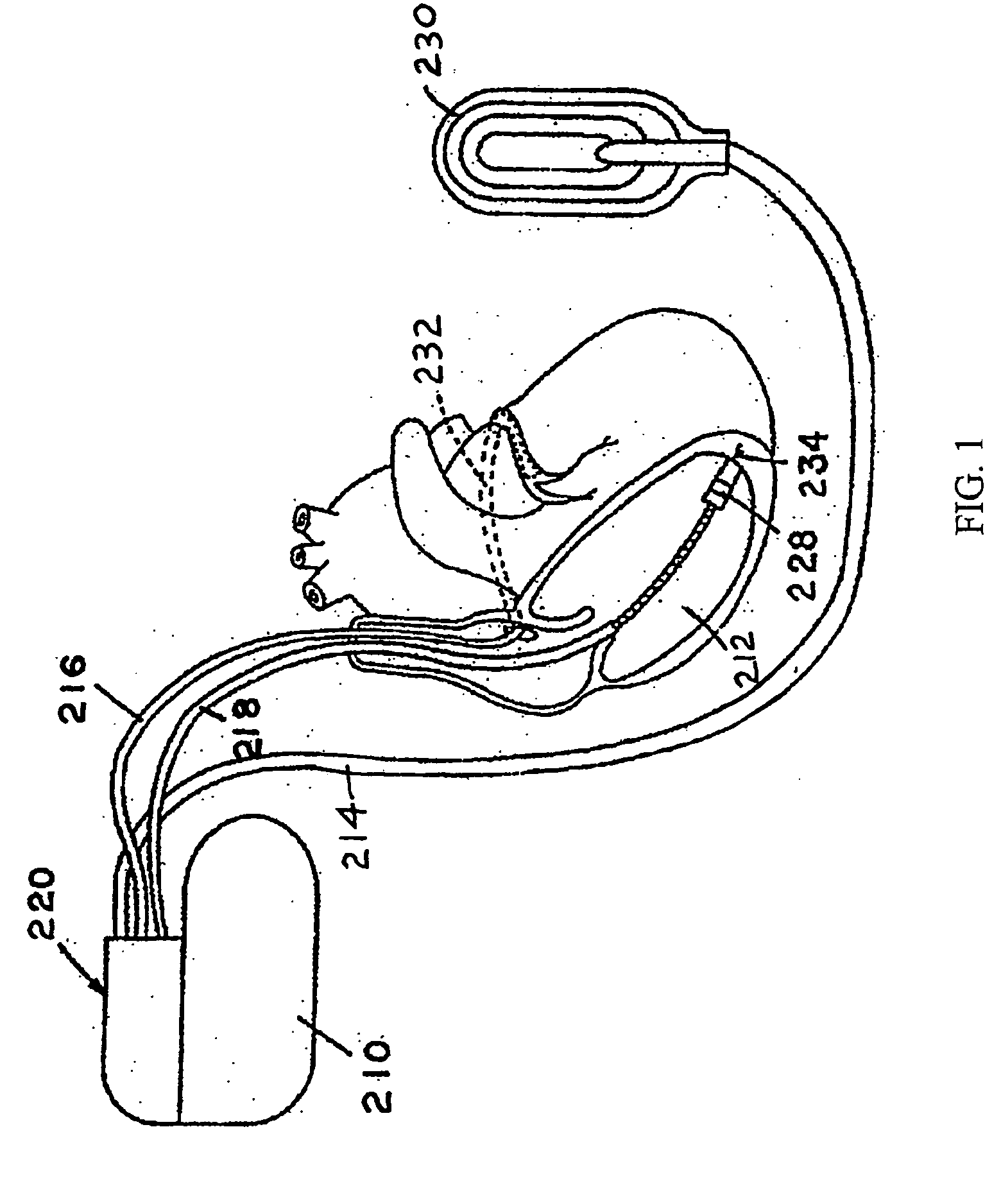
a laser welding and galvanometer technology, applied in welding apparatus, metal-working equipment, manufacturing tools, etc., can solve the problems of oxidation, brittleness, low average power delivered, etc., and achieve the effect of minimizing heat input and fast cycle times

Inactive Publication Date: 2006-07-06
MEDTRONIC INC
View PDF17 Cites 27 Cited by
  • Summary
  • Abstract
  • Description
  • Claims
  • Application Information

AI Technical Summary

Benefits of technology

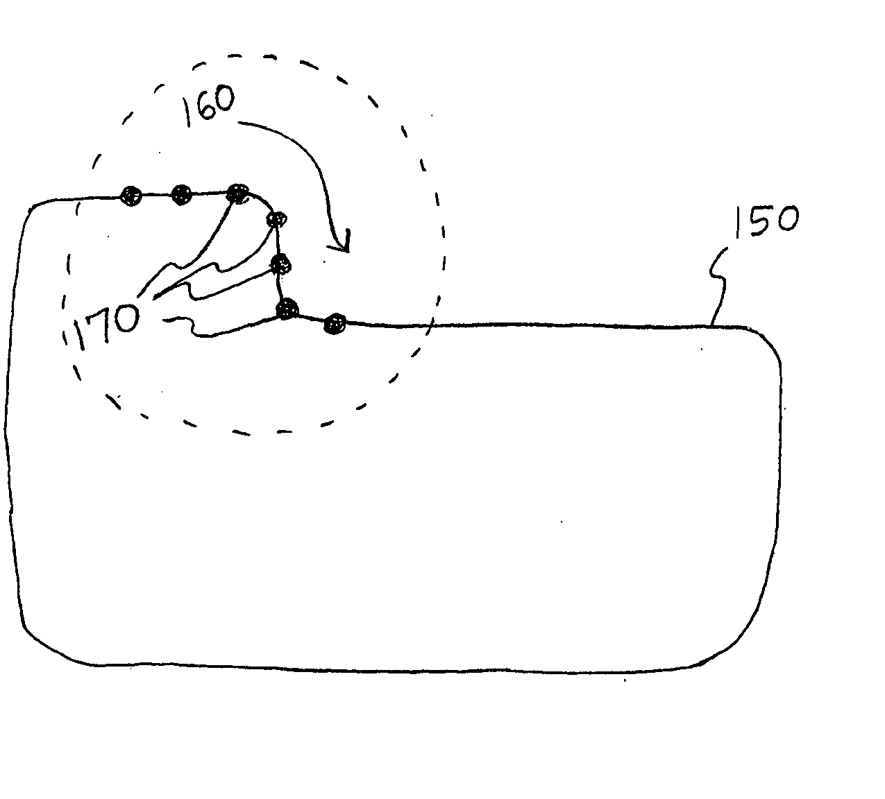
[0015] Certain embodiments of the invention provide a method of laser welding that employs a plurality of initial welding locations distributed along a desired weld path to accomplish faster cycle times while minimizing heat input. A further embodiment incorporates mirrors and galvanometer motors to direct pulses of laser beam energy in sequences of pulses that follow a specified order or pattern along a desired weld path.

Problems solved by technology

At high temperatures, chemical reactions with atmospheric gases (i.e., oxidation) can pose problems, particularly when the oxides or other elements formed have disassociation temperatures far above the melting point of the metal.
The result may be brittle, porous welds.
Pulsed laser welding employs a relatively high peak pulse energy to provide adequate weld penetration, while the intermittent nature of the pulsed energy results in a low average power delivered, which tends to reduce the total heat input.
The required amount of overlap may place constraints on how quickly successive laser pulses may be delivered without heating the device to an unacceptable level.
Pulsed YAG lasers used for seam welding on IMD components may typically operate at a maximum pulse rate of approximately 10 Hz (10 laser pulses per second), since higher pulse rates could result in unacceptable levels of heating and / or melting of components within an IMD.
Delivering laser pulses around the periphery of a component to form a hermetic weld seam may require a significant amount of time, depending on such parameters as the length of the weld path, the thermal sensitivity of nearby components, and the need for the laser pulses to overlap sufficiently to create a hermetic seal, as discussed above.
The amount of time required to perform certain welding operations, such as hermetic seal welds in IMDs and related componentry, imposes a constraint on manufacturing such devices due to the need to maintain a relatively low heat input to the device, as well as the need to achieve the degree of weld overlap necessary to achieve sufficient hermeticity.

Method used


Image

  • Method and apparatus for laser welding incorporating galvanometer delivery
  • Method and apparatus for laser welding incorporating galvanometer delivery
  • Method and apparatus for laser welding incorporating galvanometer delivery

Examples


Embodiment Construction

[0037] The following description of certain illustrated embodiments of the invention is presented to enable a person skilled in the art to appreciate certain aspects of the invention, including insubstantial modifications thereof, and to make and use the invention, as depicted and described as well as to illustrate other aspects of the invention. Various modifications to the illustrated embodiments will be readily apparent to those skilled in the art, and the generic principles herein may be applied to other embodiments and applications without departing from the spirit and scope of the invention as defined by the appended claims. Thus, the present invention is not intended to be limited to the embodiments shown, but is to be accorded the widest scope consistent with the principles and features disclosed herein. The following detailed description is to be read with reference to the figures, in which like elements in different figures have like reference numerals. The figures, which ...


PUM

PropertyMeasurementUnit
diameteraaaaaaaaaa
diameteraaaaaaaaaa
lengthaaaaaaaaaa

Abstract

Methods and systems for laser welding using a galvanometer to deliver laser energy in a multiple point sequence for high-speed and low-temperature welding of batteries, capacitors, medical devices, and related medical device components or the like.

Description

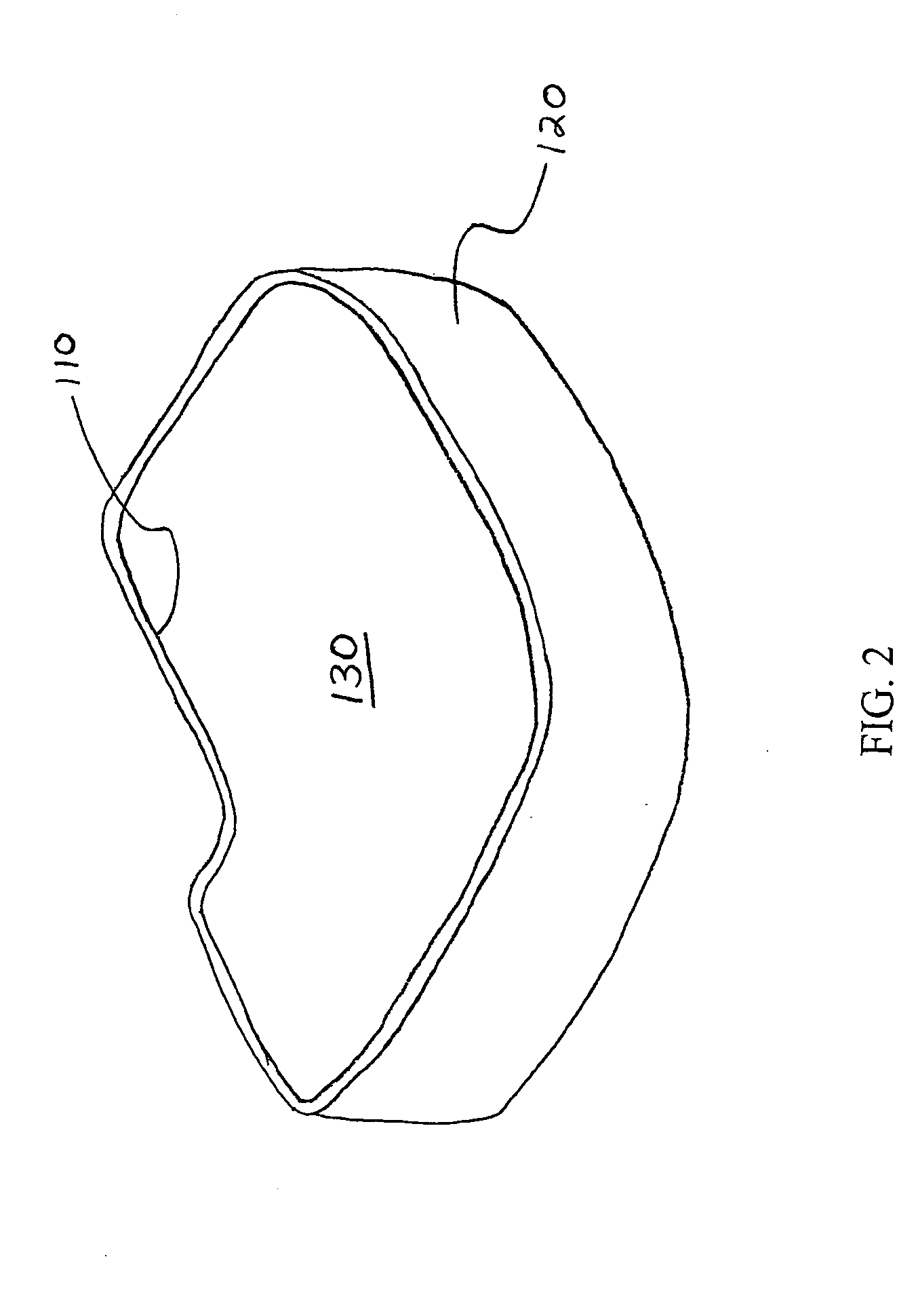
FIELD SECTION [0001] The invention relates to a method of performing laser welding and to a method of low temperature laser welding; in particular the invention pertains to methods and apparatus for welding implantable medical devices and associated components. BACKGROUND SECTION [0002] Laser welding has gained widespread acceptance in the metalworking industry, producing welds for items ranging from cigarette lighters and watch springs, to medical devices and related components, such as pacemakers, implantable defibrillators, batteries and hybrid circuit packages. Hermetic seals may be provided by laser welding processes to achieve the hermeticity required of implantable medical devices (IMDs) enclosures and associated internal components for IMDs such as batteries and capacitors. [0003] Welding requires heating materials to a molten state so that they become fused together. A laser may be employed to generate light energy that can be concentrated and absorbed at a location in mate...

Claims


Application Information

Patent Timeline
Patent Type & Authority Applications(United States)
IPC IPC(8): B23K26/28B23K26/22
CPCB23K26/22B23K26/24
Inventor PAPENFUSS, JASON T.BUENDORF, DAVID J.
Owner MEDTRONIC INC
Learn More