Multiple choke coil and electronic equipment using the same

a choke coil and electronic equipment technology, applied in the direction of transformer/inductance details, inductances with magnetic cores, inductances above circuit structures, etc., can solve the problems of increasing setup space, difficult to reduce direct-current resistance values, and insufficient realization of the increase of the above circuit structure. , to achieve the effect of reducing size and thickness

Inactive Publication Date: 2006-07-06
PANASONIC CORP
View PDF2 Cites 87 Cited by
  • Summary
  • Abstract
  • Description
  • Claims
  • Application Information

AI Technical Summary

Benefits of technology

[0043] Meanwhile, by mounting the array type choke coil on a power supply apparatus, it is possible to realize a power supply apparatus

Problems solved by technology

However, the above circuit structure solely is not necessarily sufficient in realizing the increase of current in the high-frequency band.
However, the conventional choke coil structure requires post-fixing of a metal terminal, making it difficult to reduce direct-current resistance value.
Meanwhile, arranging the foregoing coils in plurality corresponding to the number of multi-phases results in an increas

Method used


Image

  • Multiple choke coil and electronic equipment using the same
  • Multiple choke coil and electronic equipment using the same
  • Multiple choke coil and electronic equipment using the same

Examples


embodiment 1

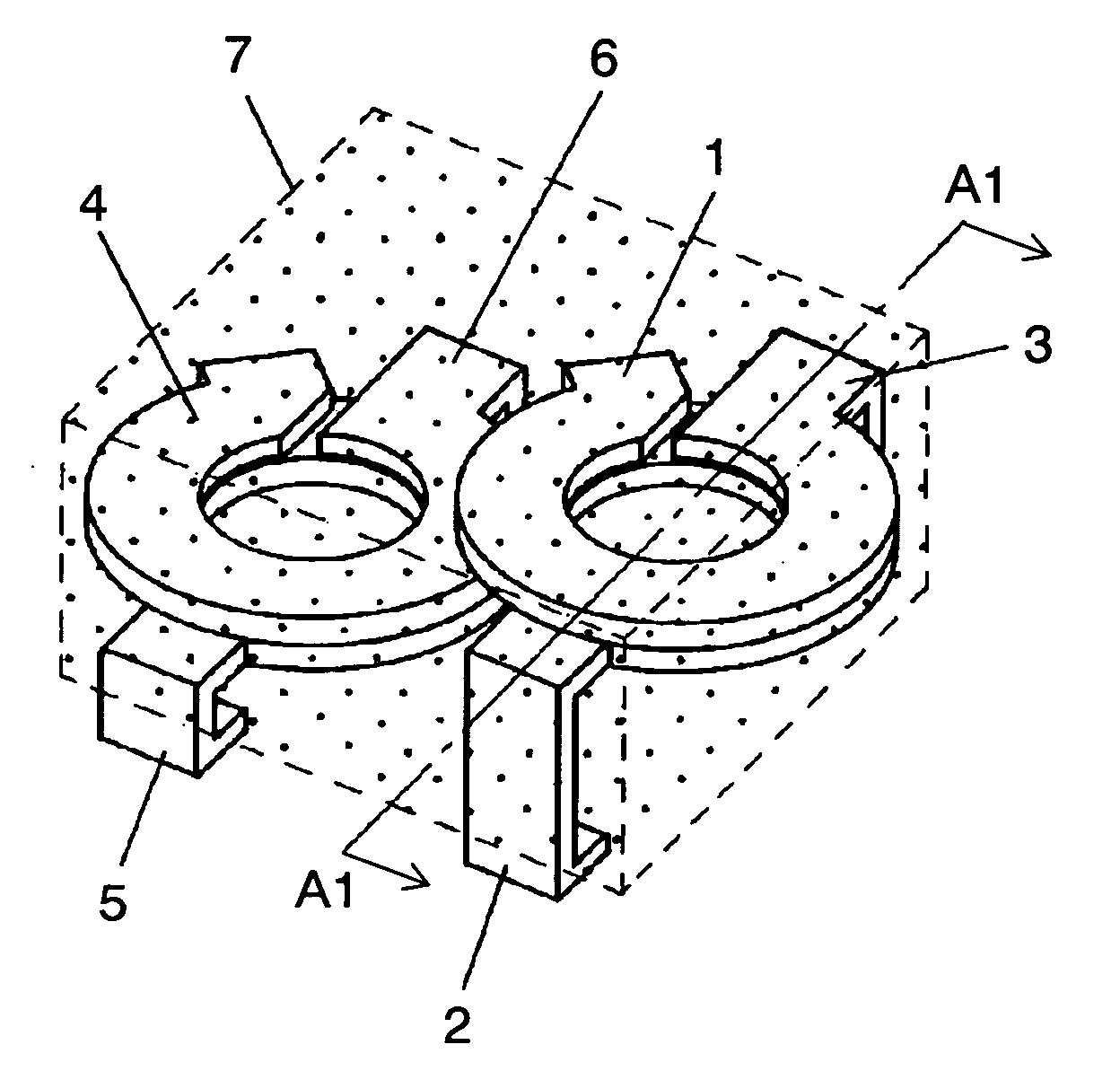
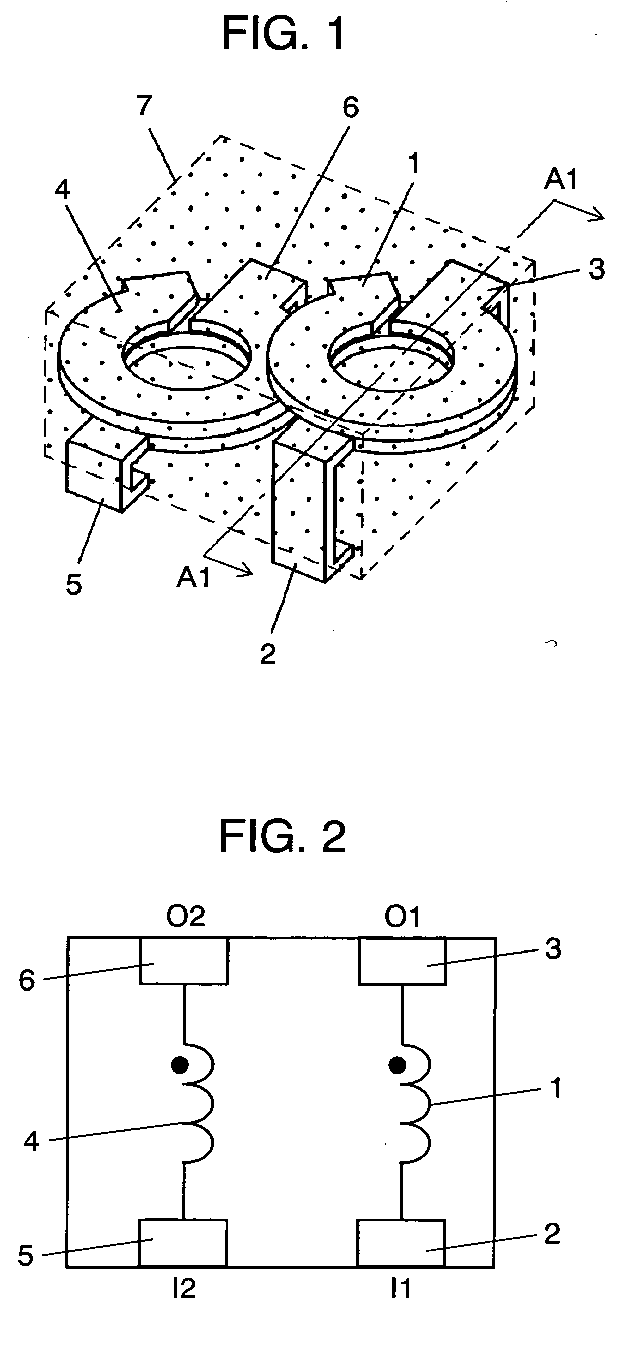
[0113]FIG. 1 is a projection perspective view of an array type choke coil in embodiment 1 of the present invention. FIG. 2 is a wiring diagram of the array type choke coil. First coil 1 is structured by being integrally formed with input terminal 2 and first output terminal 3. Second coil 4 is also structured by being integrally formed with second input terminal 5 and second output terminal 6. First coil 1 and second coil 4 are wound in the same direction, both of which have the number of turns of 1.5 turns. Due to this, in the case of flow of a current from first input terminal 2 of first coil 1 and second input terminal 5 of second coil 4, first coil 1 and second coil 4 have in-coil magnetic fluxes assuming in the same direction.

[0114] There is provided an arrangement such that an axis of first coil 1 and an axis of second coil 4 are in parallel and wherein first coil 1 is in the upper position while second coil 4 is in the lower position. Incidentally, the respective axes refer ...

embodiment 2

[0142] While referring to FIGS. 7 to 10, explanation is made on an array type choke coil in embodiment 2 of the present invention. The array type choke coil of the present embodiment is similar in basic structure to the array type choke coil in embodiment 1 of the present invention. However, the present embodiment is characterized in that a V-formed arrangement is provided by increasing by one the terminal-integrated type coils.

[0143]FIG. 7 is a projection perspective view of an array type choke coil in the present embodiment. FIG. 8 is a wiring diagram of this array type choke coil. First coil 71 is formed integrally with first input terminal 72 and first output terminal 73. Second coil 74 is similarly formed integrally with second input terminal 75 and second output terminal 76. Meanwhile, third coil 77 is formed integrally with third input terminal 78 and third output terminal 79. The respective coils are wound in the same direction, all of which have the number of turns of 1.5 ...

embodiment 3

[0169] While referring to FIGS. 15 and 16, explanation is made on an array type choke coil in embodiment 3 of the present invention. The array type choke coil of the present embodiment is similar in basic structure to the array type choke coil in embodiment 1 of the present invention.

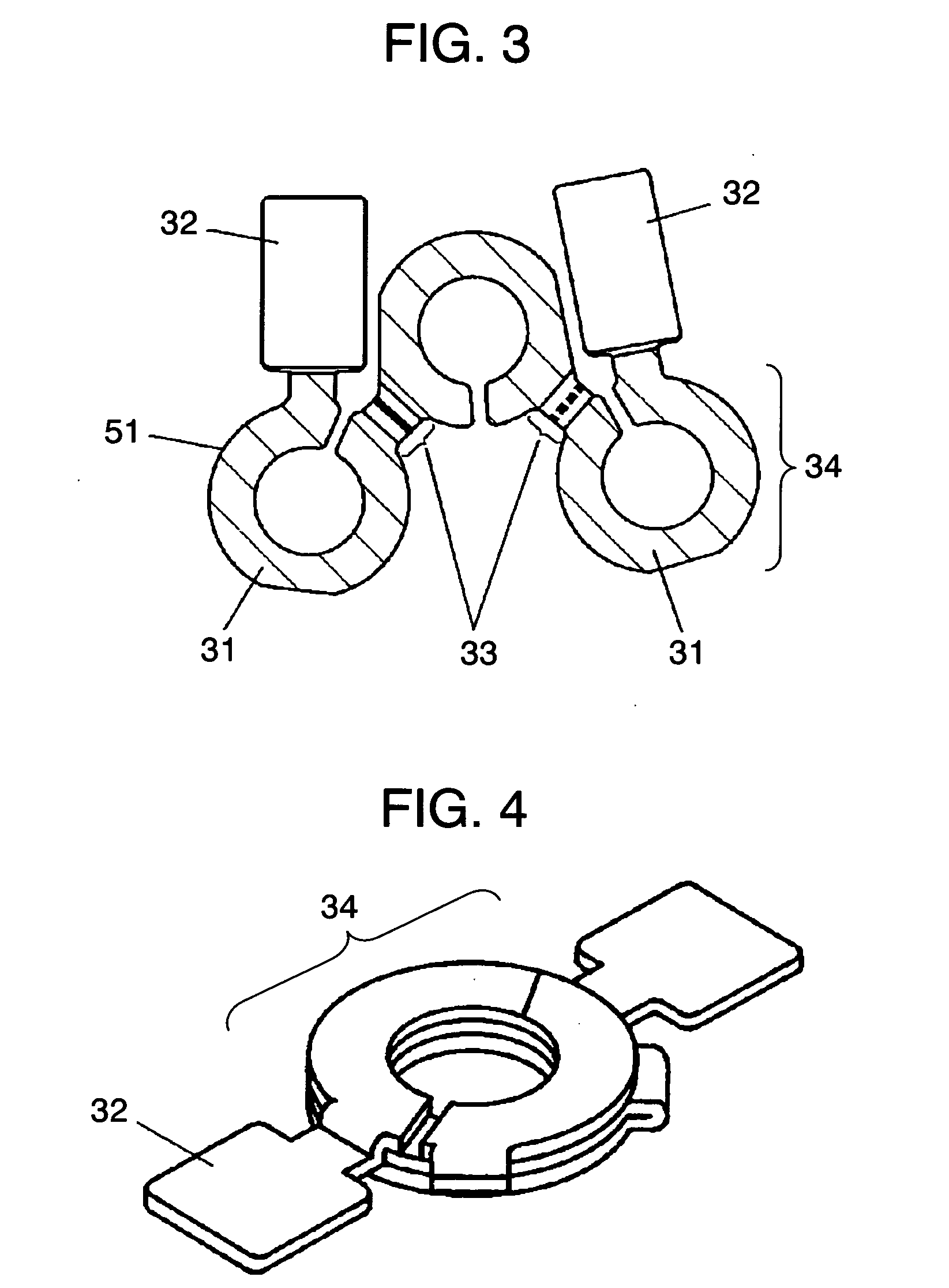
[0170]FIG. 15 is a projection perspective view of an array type choke coil in the present embodiment. First coil 131, second coil 132 and third coil 133 are terminal-integrated type coils formed by blanking and folding a metal sheet, similarly to the array type choke coil of the first embodiment. The respective coils have the number of turns of 2.5 turns.

[0171]FIG. 16 is a sectional view along the line B2-B2 in the array type choke coil shown in FIG. 15. There is provided an arrangement such that the center axis of first coil 131, the center axis of second coil 132 and the center axis of third coil 133 are in parallel and wherein first coil 131 and third coil 133 are positioned in the upper stand whil...


PUM


Abstract

The invention is comprised of a coil group arranging a plurality of terminal-integrated type coils (1), (4) formed by bending a metal sheet in a preset development form and having a predetermined positional relationship, and a magnetic material (7) burying therein the coil group. For example, axes of the plurality of coils (1), (4) constituting the coil group, are arranged in parallel wherein the center point of at least one coil selected from the plurality of coils (1), (4) and the center point of a coil other than the selected coil are in an staggered arrangement. Due to this, an array type choke coil can be realized which is thin overall and operable with a large current in a high frequency band.

Description

TECHNICAL FIELD [0001] The present invention relates to an array type choke coil for use in various electronic apparatuses and to an electronic apparatus using same, particularly a power supply apparatus. BACKGROUND ART [0002] In inductors such as choke coils, there is a desire for size and thickness reduction in order to cope with size and weight reduction of electronic apparatuses. For speed and integration increase in LSIs such as CPUs, the inductor is desired for use on large current at several amperes to several tens of amperes in the high frequency region. [0003] Accordingly, there is a desire to inexpensively supply an inductor which is reduced in size and lowered in electric resistance for suppressing heat generation, reduced in loss in high-frequency region and less in inductance value lowering due to direct current superimposition even on large current. [0004] Recently, in DC / DC converters or the like, a circuit scheme called the multi-phase scheme is adopted as a power su...

Claims


Application Information

Patent Timeline
IPC IPC(8): H01F5/00H01F17/04H01F27/02H01F27/29H01F37/00
CPCH01F27/027H01F27/292H01F37/00H01F2017/048H01F2017/065
Inventor MATSUTANI, NOBUYAIMANISHI, TSUNETSUGUUEMATSU, HIDENORI
Owner PANASONIC CORP
Why Eureka
Try Eureka