Elastic-wave monitoring device and surface-acoustic-wave device

a monitoring device and surface acoustic technology, applied in the direction of optical radiation measurement, instruments, using wave/particle radiation means, etc., can solve the problems of insufficient convenience of surface acoustic wave observation, difficult to perform the observation of surface acoustic wave in the actual sawing device, and the measurement method using the interferometer is not suitable for observing the distribution of surface acoustic waves,

Inactive Publication Date: 2006-07-06
FUJITSU LTD
View PDF14 Cites 5 Cited by
  • Summary
  • Abstract
  • Description
  • Claims
  • Application Information

AI Technical Summary

Benefits of technology

[0028] An object of the present invention is to provide an improved elastic-wave monitoring device in which the above-described problems are eliminated.
[0029] Another object of the present invention is to provide an elastic-wave monitoring device which is capable of appropriately monitoring the on-surface displacement of an elastic wave in a crystal substrate of a SAW device which has the optical anisotropy and the cut plane with a complicated angle.
[0030] Another object of the present invention is to provide an elastic-wave monitoring device and method which is capable of precisely monitoring the behavior of an elastic wave in all the ranges of the crystal substrate of the SAW device without any non-sensitive region.
[0033] According to the elastic-wave monitoring device of the present invention, it is possible to appropriately monitor the on-surface displacement of an elastic wave in the measured object, such as a SAW device, which has not been observed with the conventional elastic-wave monitoring device mentioned above.
[0036] According to the surface-acoustic-wave device of the present invention, the surface-acoustic-wave energy which has leaked out of the comb-shaped electrodes as in the conventional SAW device can be reduced, and it is possible to improve the electrical properties of the surface-acoustic-wave device.
[0039] According to the elastic-wave monitoring device and method of the present invention, it is possible to monitor the distribution of an elastic wave in all the ranges of the measured object, such as the SAW device, without any non-sensitive region, and to observe the behavior of the elastic wave more precisely.

Problems solved by technology

Therefore, the measurement method using the interferometer is not suitable for observing the distribution of the surface acoustic wave in such a SAW device.
With a simple composition like the optical modulator utilizing the electro-optic effects, it is difficult to perform the observation of the surface acoustic wave in the actual SAW device.
The change, which is detected with the composition of FIG. 1, does not necessarily appear with sufficient convenience.
It is difficult for the conventional elastic-wave monitoring device of FIG. 1 to detect a change of the surface acoustic wave in such a case.
Moreover, although it is possible for the conventional elastic-wave monitoring device of FIG. 1 to observe the distribution of the elastic wave in the SAW device, there is the problem that the behavior of the elastic wave in a non-sensitive range of the SAW device in which the light does not penetrate the SAW device cannot be observed.

Method used


Image

  • Elastic-wave monitoring device and surface-acoustic-wave device
  • Elastic-wave monitoring device and surface-acoustic-wave device
  • Elastic-wave monitoring device and surface-acoustic-wave device

Examples


Embodiment Construction

[0062] A description will now be given of preferred embodiments of the present invention with reference to the accompanying drawings.

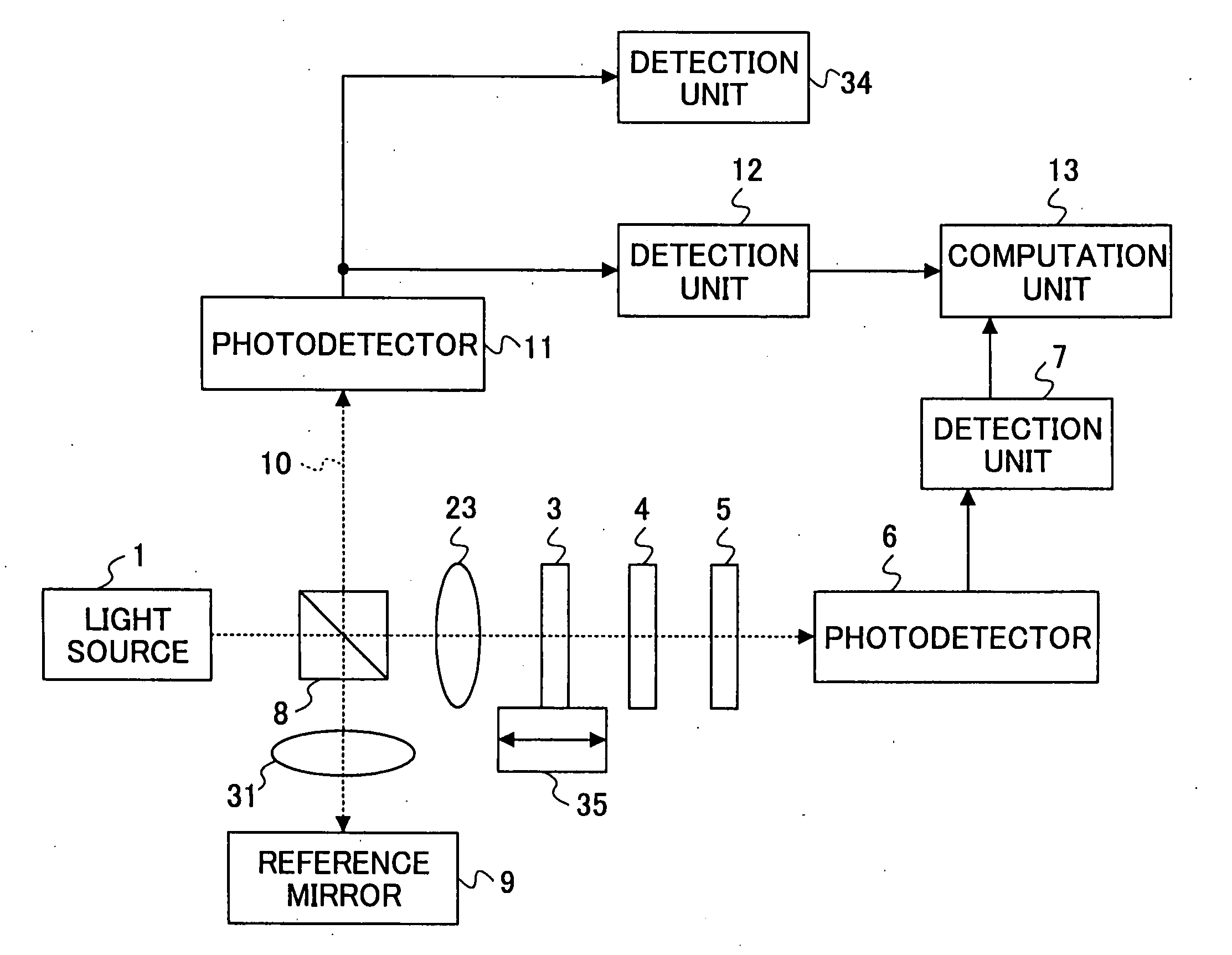
[0063]FIG. 5 shows a basic configuration of the elastic-wave monitoring device of the present invention. FIG. 6 shows the elastic-wave monitoring device in one preferred embodiment of the present invention.

[0064] In the elastic-wave monitoring device of FIG. 5, the circularly polarized light 2 from the light source is incident to the crystal 3 that is a measured object. The light 2 passes through the crystal 3, and further passes through the phase-difference compensating plate 4 and the polarizing filter 5, in this order. The resulting light from the polarizing filter 5 is received by the photodetector 6.

[0065] In the composition of FIG. 5, the polarizing filter 5 is arranged to have a polarization transmission axis 16 directed to one (as indicated by the arrow 17) of the directions of the principal axes of an ellipse formed by intersections of the ...


PUM

PropertyMeasurementUnit
refractive indexaaaaaaaaaa
wavelengthaaaaaaaaaa
reflectivityaaaaaaaaaa

Abstract

An elastic-wave monitoring device includes an optical system which is arranged so that a circularly polarized light from a light source is incident to a measured object and a light beam from the measured object passes through a polarizing filter to a photodetector. A detection unit detects periodic fluctuation components of an output signal of the photodetector. In the elastic-wave monitoring device, the polarizing filter is arranged to have a polarization transmission axis directed to one of directions of principal axes of an ellipse formed by intersections of an index ellipsoid of the measured object and a plane perpendicular to an incidence direction of the light beam and passing through an origin of the index ellipsoid.

Description

CROSS-REFERENCE TO RELATED APPLICATIONS [0001] This application is based on Japanese priority application No. 2002-109571, filed on Apr. 11, 2002, and Japanese priority application No. 2002-376742, filed on Dec. 26, 2002, the entire contents of which are hereby incorporated by reference. BACKGROUND OF THE INVENTION [0002] 1. Field of the Invention [0003] The present invention relates to an elastic-wave monitoring device which monitors the distribution of an elastic wave by performing measurement using a laser light, and to a surface-acoustic-wave device for use with the elastic-wave monitoring device. [0004] 2. Description of the Related Art [0005] SAW (surface acoustic wave) devices and related components which utilize an elastic wave, such as a surface acoustic wave, have been briskly developed. In order to study the behavior of the SAW devices and use it for improvement of the SAW devices, there is an increasing demand for the technique to observe the elastic wave. [0006] For exa...

Claims


Application Information

Patent Timeline
Patent Type & Authority Applications(United States)
IPC IPC(8): G01B11/16G01J4/00G01H9/00G01N21/21H03H9/02H03H9/145H03H9/25
CPCG01H9/00G01N21/21H03H9/02708H03H9/14544H03H9/14547
Inventor WAKANA, SHINICHIMIYAMOTO, AKINORIMATSUDA, SATORU
Owner FUJITSU LTD
Why Eureka
Try Eureka