Light guide plate, lighting illuminating device using same, area light source and display

a technology of light guide plate and lighting illuminating device, which is applied in the direction of lighting and heating apparatus, planar/plate-like light guide, instruments, etc., can solve the problems of difficult mass production difficult design of light guide plate, reflection surface, etc., and achieves easy mass production and small thickness

Inactive Publication Date: 2006-07-06
SHARP KK
View PDF6 Cites 167 Cited by
  • Summary
  • Abstract
  • Description
  • Claims
  • Application Information

AI Technical Summary

Benefits of technology

[0011] In order to solve the above problems, an object of the present invention is to provide a light guide plate capable of converting a point light source and / or a liner light source into a planar light source, which light guide plate is made with a smaller thickness than the conventional plate, and allows easy mass production. The light guide plate of the present invention with such advantages is constituted by stacking a plurality of light guide layers whose refractive indices are different from each other.

Problems solved by technology

However, because of the low color rendering property (color reproducibility) of a white LED, a backlight using a light source of white LED is not frequently used as the light source of general illumination.
However, these conventional configurations have the following problems.
Moreover, in the case of the light guide plate described as the second conventional art, the designing of the light guide plate (for example, reflection surface) is extremely difficult if attempting to achieve an uniform surface luminance.
Therefore, mass production of the light guide plates is difficult if the same quality is required.

Method used


Image

  • Light guide plate, lighting illuminating device using same, area light source and display
  • Light guide plate, lighting illuminating device using same, area light source and display
  • Light guide plate, lighting illuminating device using same, area light source and display

Examples


embodiment 1

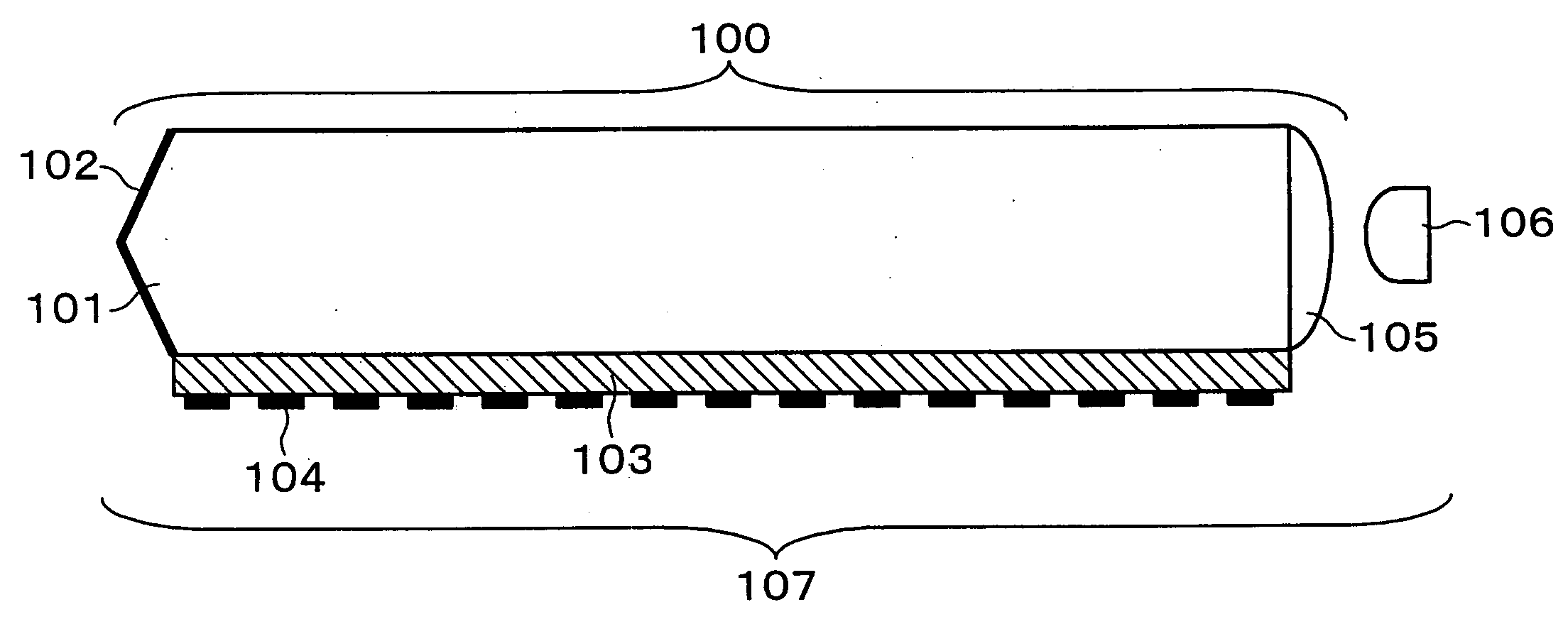
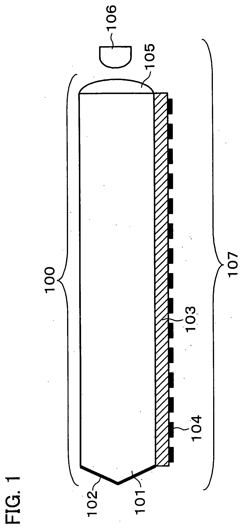
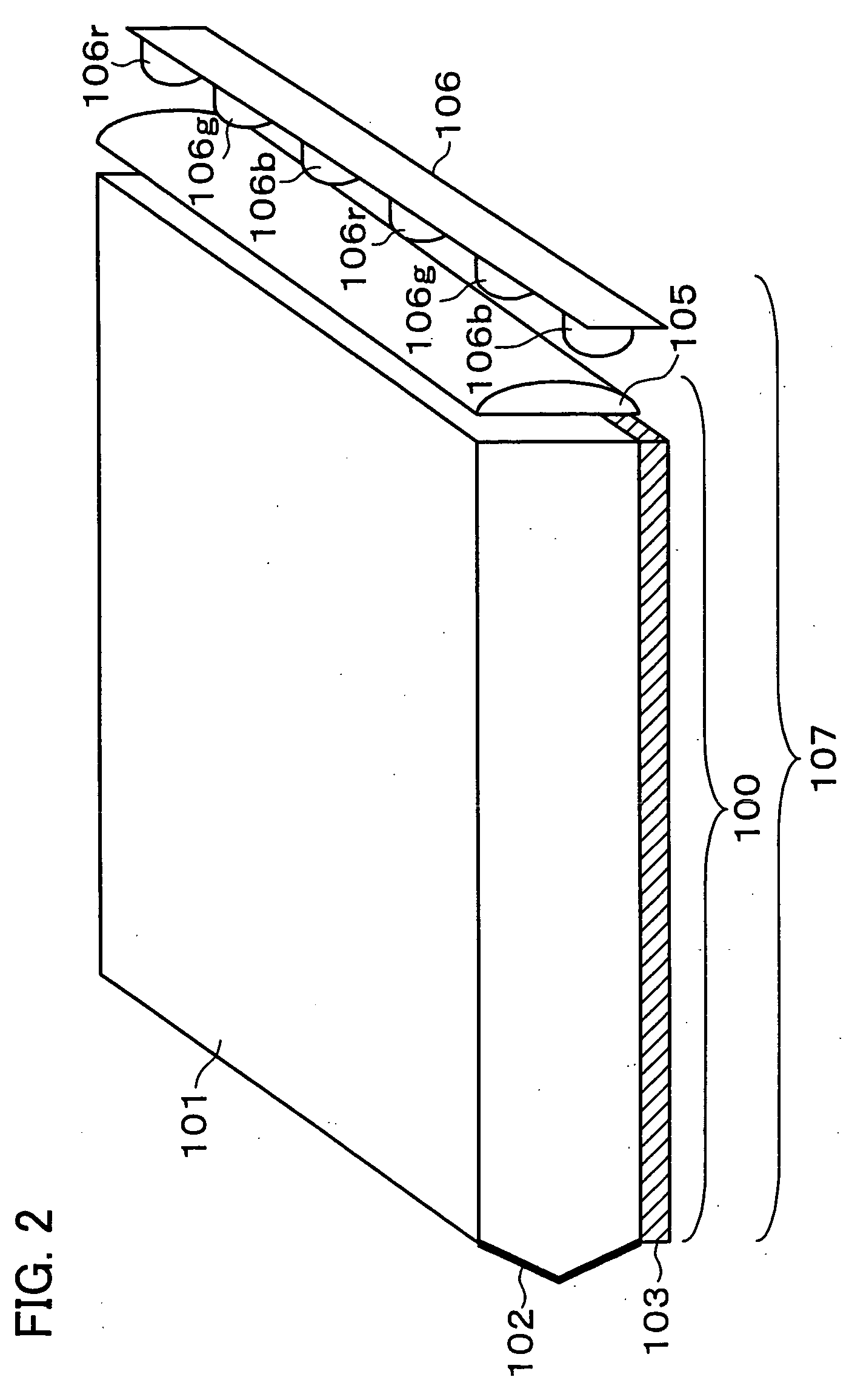
[0041] The following explains Embodiment 1 of the present invention in reference to the figures. A light guide plate of the present embodiment includes (i) the first light guide layer made of a material having a refractive index n1, the first light guide layer receiving light from a light source which is distributed in a certain range of angles with respect to the light guide plate, and (ii) a scattering light guide layer which emits, as scattering light, the light having been incident on the first light guide layer. The first light guide layer and the scattering light guide layer are stacked perpendicularly to the direction of light propagation in a first light guide layer. Moreover, the light guide plate of the present embodiment is so structured that (i) the scattering light guide layer includes at least (a) a second light guide layer adjacent to the first light guide layer and made of a material having a refractive index n2 lower than the refractive index n1 and (b) a scattering...

embodiment 2

[0079] The following explains another embodiment of the present invention in reference to FIG. 7. Note that, for ease of explanation, the same reference numerals are used for the members having the same functions as the members used in Embodiment 1, and the explanations thereof are omitted.

[0080]FIG. 7 is a side view showing a schematic arrangement of a light guide body 120 and a lighting apparatus 127 of the present embodiment. In Embodiment 2, the light guide plate 120 includes, as basic members, the first light guide body 101 having the refractive index n1, the second light guide body 103 having the refractive index n2 lower than the refractive index n1, a third light guide body 110 having a refractive index n3 higher than the refractive index n2, the reflection section 102, and the reflection dots 104. The second light guide body 103 is formed between the first light guide body 101 and the third light guide body 110, and those light guide bodies are optically connected with eac...

embodiment 3

[0090] The following explains another embodiment of the present invention in reference to FIG. 8. Note that, for ease of explanation, the same reference numerals are used for the members having the same functions as the members used in Embodiments 1 and 2, and further explanations thereof are omitted. The present embodiment explains an example providing, in addition to the above arrangement, a scattering layer, by forming depressions and projections on a surface of the scattering light guide layer which is constituted of the second light guide body, the surface opposite to a surface in contact with the first light guide body.

[0091]FIG. 8 is a side view showing a schematic arrangement of a light guide plate 130 and a lighting apparatus 137 of the present embodiment. In Embodiment 3, the light guide plate 130 includes, as basic members, the first light guide body 101 having the refractive index n1, the second light guide body 103 having the refractive index n2 lower than the refracti...


PUM


Abstract

A light guide plate includes (i) a first light guide layer made of a material having a refractive index n1, and (ii) a scattering light guide layer having a function of scattering light. A reflection means for irradiating the scattering light guide layer with the light having propagated in the first light guide layer is provided on a surface opposite to a light guide surface of the first light guide layer, the light guide surface on which the light is incident. The scattering light guide layer includes at least (i) a second light guide layer made of a material having a refractive index n2 (n2<n1), and (ii) a scattering layer for scattering the light propagating in the second light guide layer.

Description

TECHNICAL FIELD [0001] The present invention relates to a light guide plate and a lighting apparatus capable of changing light from a point light source or a linear light source into a planar light source. BACKGROUND ART [0002] In recent years, semiconductor light sources, such as LEDs (Light Emitting Diode) and LDs (Laser Diode) has been significantly improved in performance, especially in luminance and luminous efficiency. In addition, the semiconductor light sources originally have advantages, such as high color purity and a long life. Therefore, the semiconductor light sources are being utilized as a light source of illumination. Especially, in comparison with conventional light sources, the semiconductor light sources can increase color reproducibility. On this account, application of the semiconductor light source to a backlight of a liquid crystal display, an electric poster, or the like has attracted attention. [0003] However, because of the low color rendering property (col...

Claims


Application Information

Patent Timeline
Patent Type & Authority Applications(United States)
IPC IPC(8): F21V7/04F21V8/00
CPCG02B6/0018G02B6/003G02B6/0036G02B6/0041G02B6/0043G02B6/0046
Inventor IWAUCHI, KENICHIWAKABAYASHI, YASUTAKAOOHARA, AKEMIYAMANAKA, ATSUSHI
Owner SHARP KK
Why Eureka
Try Eureka