Eureka AIR delivers breakthrough ideas for toughest innovation challenges, trusted by R&D personnel around the world.

Double silver low-emissivity and solar control coatings

a technology of solar control and low emissivity, applied in the field of low emissivity coatings, can solve the problems thin transparent metal film of ag, unable to provide the extreme reflected color required for aesthetic and other reasons by certain applications, and achieves the effects of reducing visible transmission, reducing emissivity, and ensuring the appearance of the surfa

Inactive Publication Date: 2006-07-06
AGC FLAT GLASS NORTH AMERICA INC
View PDF99 Cites 31 Cited by
  • Summary
  • Abstract
  • Description
  • Claims
  • Application Information

AI Technical Summary

Benefits of technology

The present invention provides a multilayer coating that can reduce the infrared emissivity of a substrate while maintaining minimal visible transmittance. The coating can be designed to exhibit a wide variety of different colors in reflection. The first layer of titanium oxide or silicon nitride provides excellent barrier properties against oxygen and alkaline ions migrating from the substrate, as well as a smooth surface for deposition of thinner pin-hole free Ag films with higher visible transmission. The second and fourth layers of zinc oxide and oxidized metal provide a substrate for relatively thin, high electrical conductivity, Ag films and protect against oxygen, water, and other reactive atmospheric gases. Dividing the layers with a sublayer of oxidized metal improves strength and mechanical stability during heat treatments. The fifth layer of silicon nitride enhances resistance to scratching. The multilayer coatings can undergo heat treatments with minimal mechanical or optical degradation.

Problems solved by technology

However, conventional low-emissivity coatings fail to provide the extremes of reflected color required for aesthetic and other reasons by certain applications.
However, increasing Ag film thickness will also cause visible transmission to decrease.
Thin, transparent metal films of Ag are susceptible to corrosion (e.g., staining) when they are brought into contact, under moist or wet conditions, with various staining agents, such as atmosphere-carried chlorides, sulfides, sulfur dioxide and the like.
However, the protection provided by conventional barrier layers is frequently inadequate.
These thermal treatments can cause the optical properties of Ag coatings to deteriorate irreversibly.
This deterioration can result from oxidation of the Ag by oxygen diffusing across layers above and below the Ag.
The deterioration can also result from reaction of the Ag with alkaline ions, such as sodium (Na+), migrating from the glass.
However, multilayer coatings employing Ag as an infrared reflective film frequently cannot withstand such temperatures without some deterioration of the Ag film.

Method used


Image

  • Double silver low-emissivity and solar control coatings
  • Double silver low-emissivity and solar control coatings
  • Double silver low-emissivity and solar control coatings

Examples


example 1

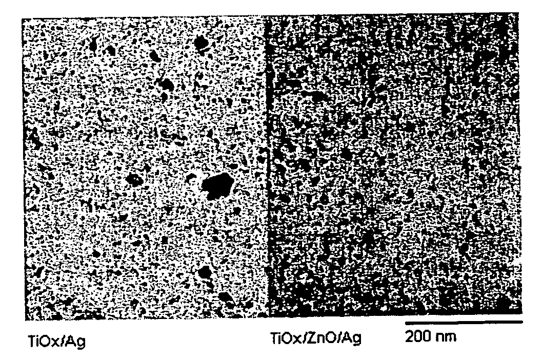
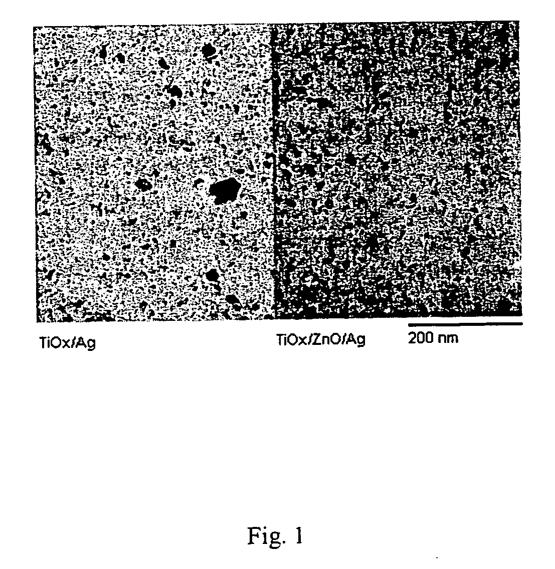
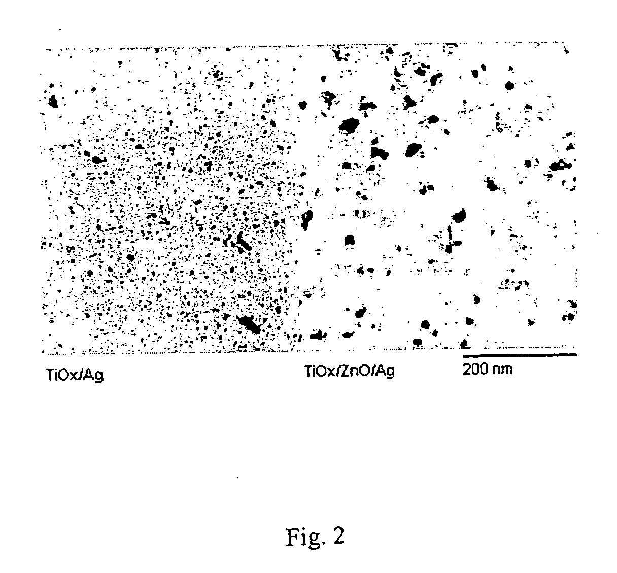
[0052] As discussed above, a sublayer of zinc oxide deposited on amorphous titanium oxide promotes the wetting of Ag on the zinc oxide and the formation of thinner layers of pin-hole free Ag.

[0053] To demonstrate this, Ag films 16 nm thick were planar DC magnetron sputter deposited onto amorphous TiOx (a-TiOx) underlayers 25 nm thick, and also onto ZnO (5 nm) / a-TiOx (25 nm) under(bi)layers. Transmission electron diffraction micrographs of the amorphous TiOx showed only broad diffuse rings, indicating that the TiOx was amorphous. The ZnO and a-TiOx dielectric layers were reactively sputtered from metal targets. The substrates for the a-TiOx layers included glass, and transmission electron microscopy (TEM) grids each having a 50 nm thick, amorphous, silicon nitride, electron transparent membrane peripherally supported by Si. The membrane was formed in a manner well known in the art by depositing silicon nitride by LPCVD (liquid phase chemical vapor deposition) onto a Si wafer, and th...

example 2

[0059] A complex structure incorporating many of the features of the present invention appears in Table 6.

TABLE 6LayerMaterial*5SiNx4c(2)NiCrOx4b(2)Ag4c(1)NiCrOx4b(1)Ag4aZnOx3cTiOx3bNiCrOx3aTiOx, SiNx, or superlattice2c(2)NiCrOx2b(2)Ag2c(1)NiCrOx2b(1)Ag2aZnOx1a(2)TiOx1bNiCrOx1a(1)TiOx, SiNx, or superlattice0glass substrate

*In Table 6, the subscript “x” indicates both stoichiometic and sub-stoichiometric compositions.

[0060] Various multilayer coatings including all, or a portion, of the layers shown in Table 6 were made by DC magnetron sputtering.

[0061] It was found that by varying the thicknesses of the silicon nitride and titanium oxide layers the reflected color of the coating can be positioned in any of the four color coordinate quadrants of the CEE 1976 L*a*b* (CIELAB) and CIE 1931 Yxy (Chromaticity) color spaces. Techniques and standards for quantifying the measurement of color are well known to the skilled artisan and will not be repeated here.

[0062]FIGS. 4a-4c show trans...


PUM

PropertyMeasurementUnit
thickaaaaaaaaaa
thickaaaaaaaaaa
thickaaaaaaaaaa

Abstract

A low-emissivity multilayer coating includes, in order outward from the substrate, a first layer including a layer containing titanium oxide, a layer containing silicon nitride, or a sublayer layer containing titanium oxide in combination with a sublayer containing silicon nitride; a second layer including Ag; a third layer including at least one layer selected from titanium oxide layers and silicon nitride layers; a fourth layer including Ag; and a fifth layer including silicon nitride. The color of the coatings can be varied over a wide range by controlling the thicknesses of the layers of titanium oxide, silicon nitride and Ag. A diffusion barrier of oxidized metal protects relatively thin, high electrical conductivity, pinhole free Ag films grown preferentially on zinc oxide substrates. Oxygen and / or nitrogen in the Ag films improves the thermal and mechanical stability of the Ag. Dividing the first layer of titanium oxide, the Ag layers, and / or the third layer with a sublayer of oxidized metal can provide greater thermal and mechanical stability to the respective layers.

Description

BACKGROUND OF THE INVENTION [0001] 1. Field of the Invention [0002] The present invention relates to low emissivity coatings. More specifically, the present invention relates to multilayer coatings for controlling thermal radiation from substrates transparent to visible light. [0003] 2. Discussion of the Background [0004] Solar control coatings on transparent panels or substrates are designed to permit the passage of visible light while blocking infrared (IR) radiation. High visible transmittance, low emissivity coatings on, e.g., architectural glass and automobile windows can lead to substantial savings in costs associated with environmental control, such as heating and cooling costs. [0005] Generally speaking, coatings that provide for high visible transmittance and low emissivity are made up of a stack of films. The stack includes one or more thin metallic films, with high IR reflectance and low transmissivity, disposed between anti-reflective dielectric layers. The IR reflective...

Claims


Application Information

Patent Timeline
Patent Type & Authority Applications(United States)
IPC IPC(8): B05D1/36B32B17/06B32B19/00B32B9/00C03C17/36G02B5/28
CPCC03C17/36C03C17/3618C03C17/3626C03C17/3639C03C17/3644Y10T428/24975C03C17/366C03C2217/78G02B5/282Y10T428/265Y10T428/12618C03C17/3652
Inventor GLENN, DARINJOHNSON, HERBDANNENBERG, RANGSIECK, PETER A.COUNTRYWOOD, JOE
Owner AGC FLAT GLASS NORTH AMERICA INC
Why Eureka
Eureka Blog
Learn More