
Capacitive uterine contraction sensor

Inactive Publication Date: 2006-07-06
GENERAL ELECTRIC CO +1
View PDF40 Cites 49 Cited by
  • Summary
  • Abstract
  • Description
  • Claims
  • Application Information

AI Technical Summary

Benefits of technology

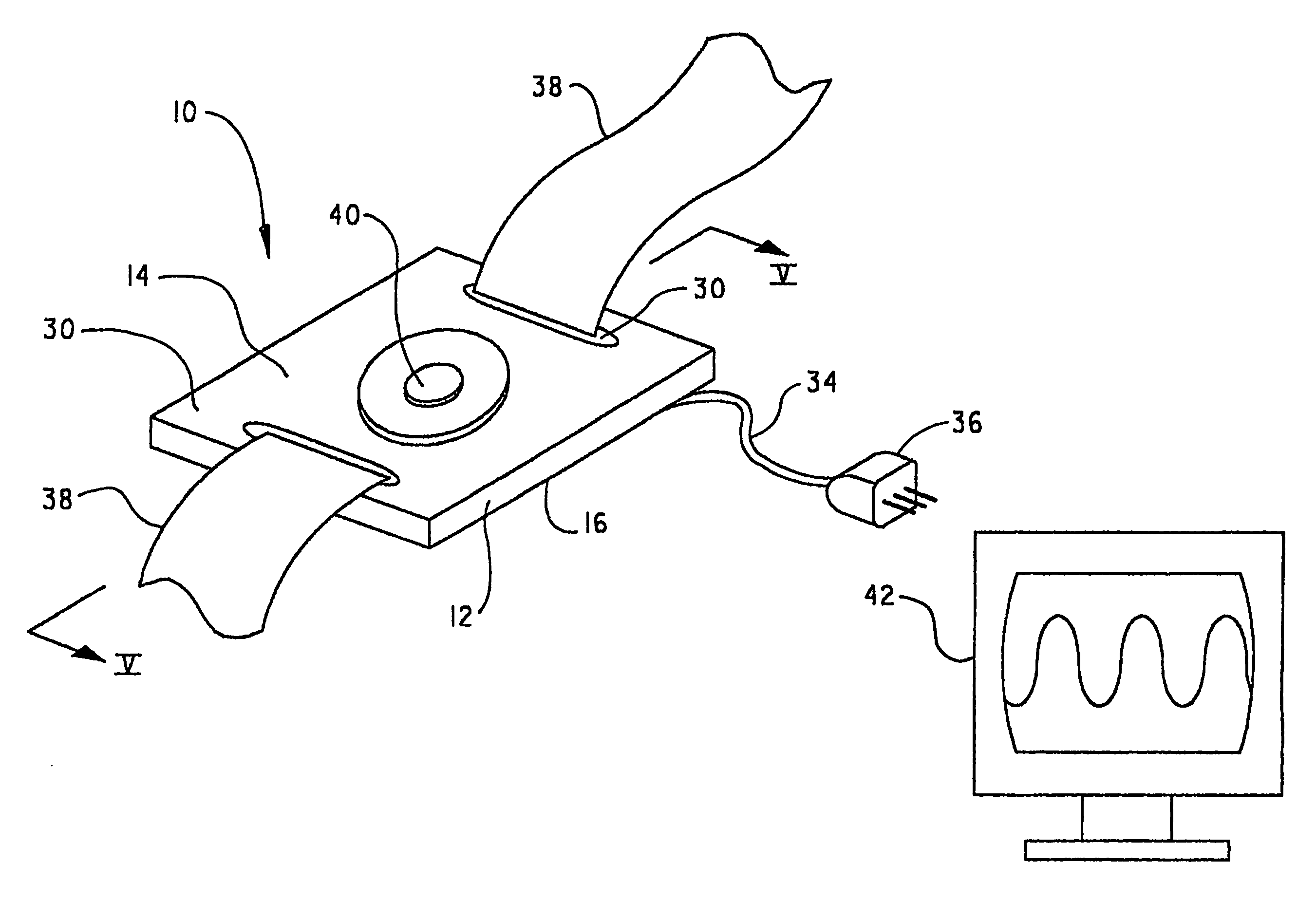
[0011] The first electrode is held stationary with respect to the base, while the second electrode is allowed to move relative to the first electrode. The relevant movement is enabled through the use of a spring mechanism or the elastic deflection of a non-stationary electrode under an applied load. The change in distance between the electrodes varies the gap and, therefore, the capacitance, between the electrodes. If a higher level of sensitivity or a smaller size is required, the gap can be filled with a dielectric fluid or deformable dielectric material. An electronic circuit connects to the capacitive sensing device and properly scales the change in capacitance and outputs the scaled result to a monitor or like device capable of displaying the desired information regarding the strength of the contraction. A shield eliminating the electrical influence of external objects can be placed around the electrodes to further improve the performance of the device.

Problems solved by technology

However, these devices are invasive and therefore they cannot be used for pre-term monitoring.
Tocotonometers are expensive, structurally delicate, i.e., break easily, and are difficult to sanitize between uses.
Like tocotonometers, these devices are expensive, complicated in construction and use, and difficult to sanitize between uses.

Method used


Image

  • Capacitive uterine contraction sensor
  • Capacitive uterine contraction sensor
  • Capacitive uterine contraction sensor

Examples


Embodiment Construction

[0026] The present invention will be described with reference to the accompanying figures, where like reference numbers correspond to like elements. It is to be understood that the attached figures and the following specification are for the purpose of describing the invention and are not to be construed as limiting the invention.

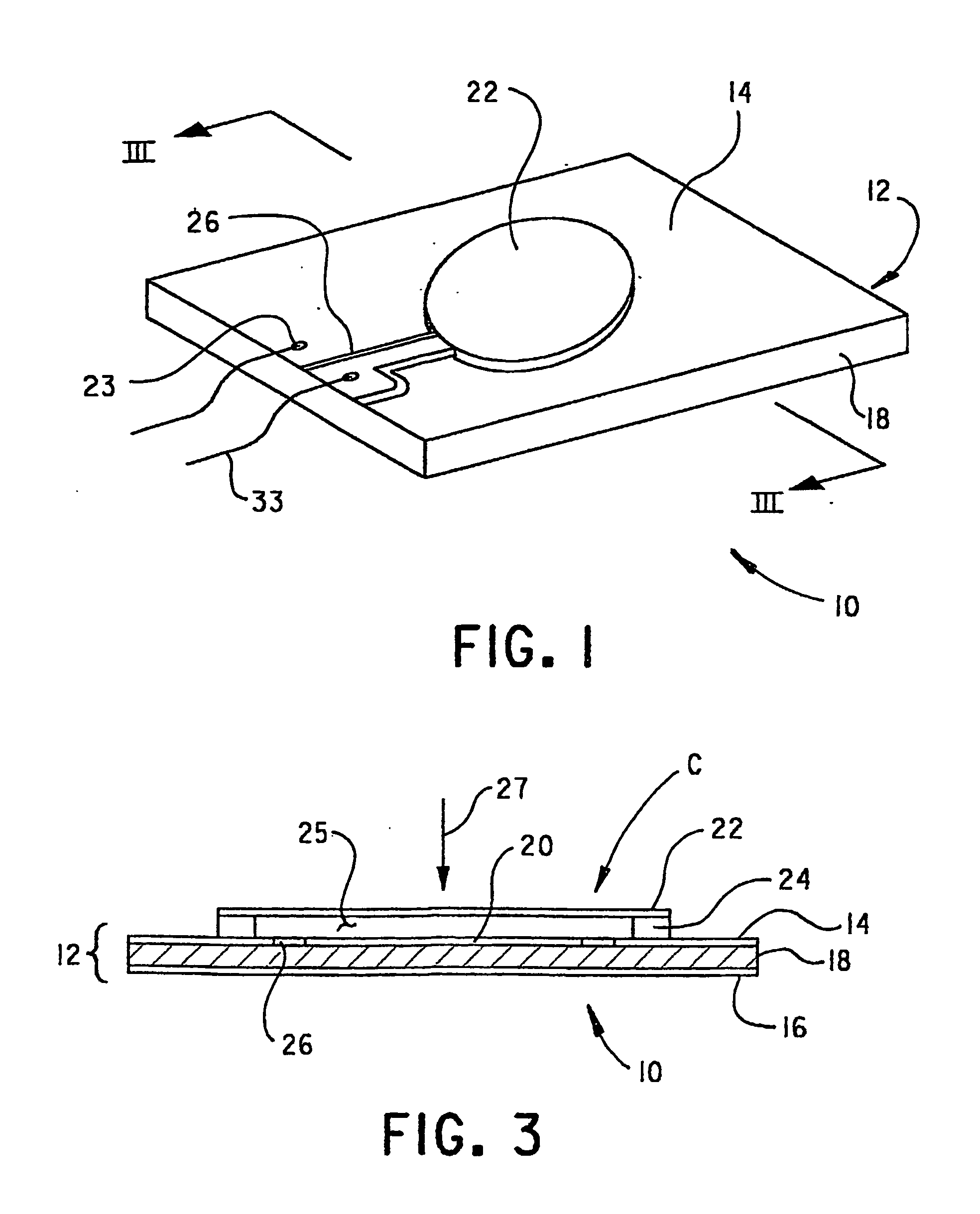
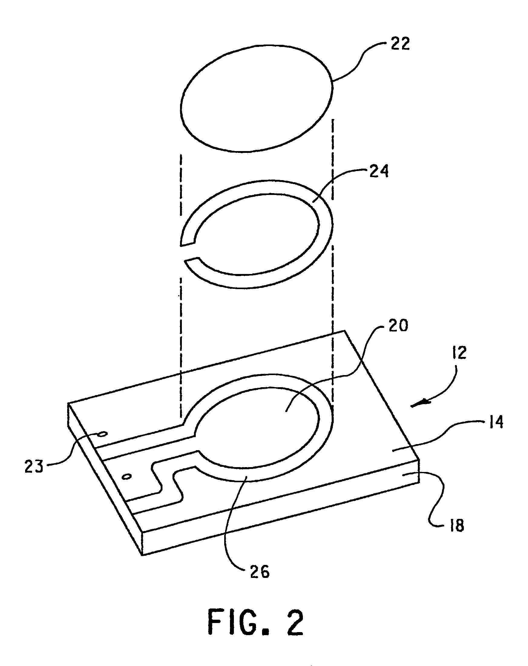
[0027]FIGS. 1-3 are views of a first embodiment capacitive sensing element 10, with FIG. 2 illustrating an exploded view of the component parts thereof. Sensing element 10 includes a printed circuit board 12, having a copper top 14, a copper base 16, and an insulating, e.g., fiberglass, substrate 18. An electrically isolated stationary electrode 20 is defined in copper top 14 by removing, e.g., etching, a suitable portion of copper top 14 to form therein a crevice 26 having as its base an exposed portion of substrate 18. An exemplary thickness of printed circuit board 12 is 1.6 mm, so as to allow for an appropriate thickness of copper top 14, copper base 1...


PUM


Abstract

A capacitive uterine contraction sensor (28) includes an insulating substrate (18), a first electrode (20) disposed on one side of the substrate (18), and a second electrode (22) positioned in a spaced relation to the first electrode (20). The second electrode (22) is configured to move toward or away from the first electrode (20). The sensor may also include a conductive standoff (24) sandwiched between the substrate (18) and the second electrode (22) for maintaining the second electrode (22) in a spaced relation to the first electrode (20). The conductive standoff (24) is electrically coupled to the second electrode (22) and electrically isolated from the first electrode (20). Alternatively, the second electrode (22) may include a spring mechanism used in conjunction with a standoff (24) to maintain the second electrode (22) in a spaced relation to the first electrode (20). The spring mechanism is electrically isolated from the first electrode (20) and enables the second electrode (22) to move toward or away from the first electrode (20).

Description

BACKGROUND OF THE INVENTION [0001] 1. Field of the Invention [0002] This invention relates generally to fetal monitoring apparatuses and, more particularly, to an apparatus for sensing uterine activity, in particular, contractions. [0003] 2. Description of the Prior Art [0004] Fetal monitors, which are typically quite sophisticated, are widely used to monitor the uterine activity of pregnant women, as well as the condition of the fetus and the uterus. Analysis of uterine contractions, in conjunction with fetal heart rate, during pregnancy and labor yields significant information concerning the condition of the fetus as well as the advancement of labor. Such monitoring is particularly helpful in so-called difficult pregnancies to systematically evaluate fetal stress, but it is certainly of use in more routine pregnancies as well. [0005] Information of fetal distress will result in prompt remedial action, including a cesarean delivery, both during pregnancy and / or during actual labor....

Claims


Application Information

Patent Timeline
IPC IPC(8): A61B5/103A61B5/04A61B5/03A61B5/0488
CPCA61B5/04882A61B5/4356A61B2562/02A61B5/391
Inventor CZARNEK, ROBERT
Owner GENERAL ELECTRIC CO
Learn More