LED lighting system

a technology of led lighting and leds, applied in the direction of electric variable regulation, process and machine control, instruments, etc., can solve the problems of artificially low luminous efficiency difficult to determine the true efficiency increase associated with leds operating at lower power levels, etc., to maximize the efficiency and effect of such systems

Inactive Publication Date: 2006-07-06
SOLARONE SOLUTIONS
View PDF17 Cites 121 Cited by
  • Summary
  • Abstract
  • Description
  • Claims
  • Application Information

AI Technical Summary

Benefits of technology

[0012] A LED lighting system, according to an embodiment of the present invention, includes at least one LED having a maximum current capacity, and at least one constant-current driver for supplying a substantially constant current to the at least one LED, whereby luminous efficiency of the LED lighting system is increased.
[0014] The present inventors have also discovered that adjusting the various color constituents of a multiple-color LED lighting system enhances both the efficiency and effectiveness of an LED lighting system under a range of ambient light conditions. These advantageous adjustments of the various color constituents are particularly well-suited for use in connection with LED lighting systems using CCDs for control of luminous intensity, though other current control means may also be used. The response of the human eye to various wavelengths of light differs depending on the ambient light conditions. This varying response is at least partially due to the two basic light-receptive structures in the eye, rods and cones. Cones tend to be more active in brightly-lit ambient conditions, whereas rods are more active in dimly-lit ambient conditions. FIG. 1 illustrates the response of the eye under a range of ambient lighting conditions. In relatively dark, or scotopic, ambient conditions, below approximately 1×10² candellas / meter squared (cd / m2), the rods predominate. In relatively bright, or photopic, ambient conditions, above approximately 1.0×101 cd / m2 the cones predominate. Between scotopic and photopic conditions are mesopic conditions, in which optical response is largely due to the combined response of rods and cones.
[0018] The efficiency and effectiveness of such a system is further enhanced, in another aspect of the present invention, by including a light detection means for detecting an ambient light condition, wherein said programmable controller includes a spectrum adjustment routine for adjusting at least one of said first and second adjustable intensities to produce an overall spectrum in response to said ambient light condition.
[0019] The efficiency of a LED lighting system is also enhanced, in a further aspect of the present invention, wherein said first LED has a greater luminous efficiency than said second LED, and said programmable controller includes an efficiency enhancement routine for increasing an overall efficiency of said LED lighting system by operating said first LED at a higher intensity relative to said second LED.
[0023] Given the potentially long distances that may exist between the LEDs, the constant current driver and the programmable controllers in LED lighting systems, an additional embodiment of the present invention further optimizes the efficiency and effectiveness of such systems by providing an LED assembly, including an LED and a current control menas, and a programmable controller adapted for optical communications and a fiber optic line for carrying optical communications between the two. Additional fiber optic lines are provided for optical communications between the programmable controller and other system components.
[0024] According to another embodiment of the present invention, An LED lighting system comprising a least one LED, a battery, a limited-capacity power source for charging said battery, a charge controller including an MPPT routine for maximizing the rate at which said power source charge said battery in sub-optimal charging conditions.

Problems solved by technology

Determining the true efficiency increase associated with LEDs operating at lower powers was particularly difficult because most commercially-available LED arrays contain “built-in” balancing resistors.
A side-effect of such resistors is to create an artificial efficiency peak where circuit impedances were matched, resulting in artificially low luminous efficiencies at lower power levels.

Method used


Image

  • LED lighting system
  • LED lighting system
  • LED lighting system

Examples


Embodiment Construction

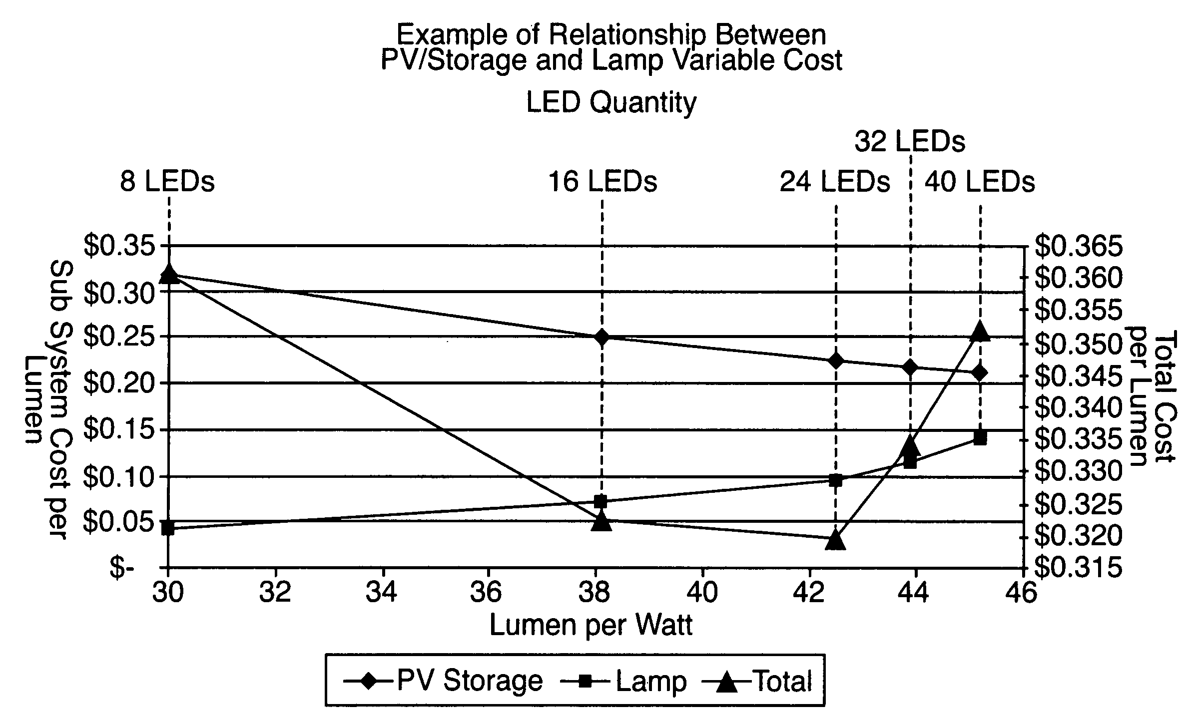
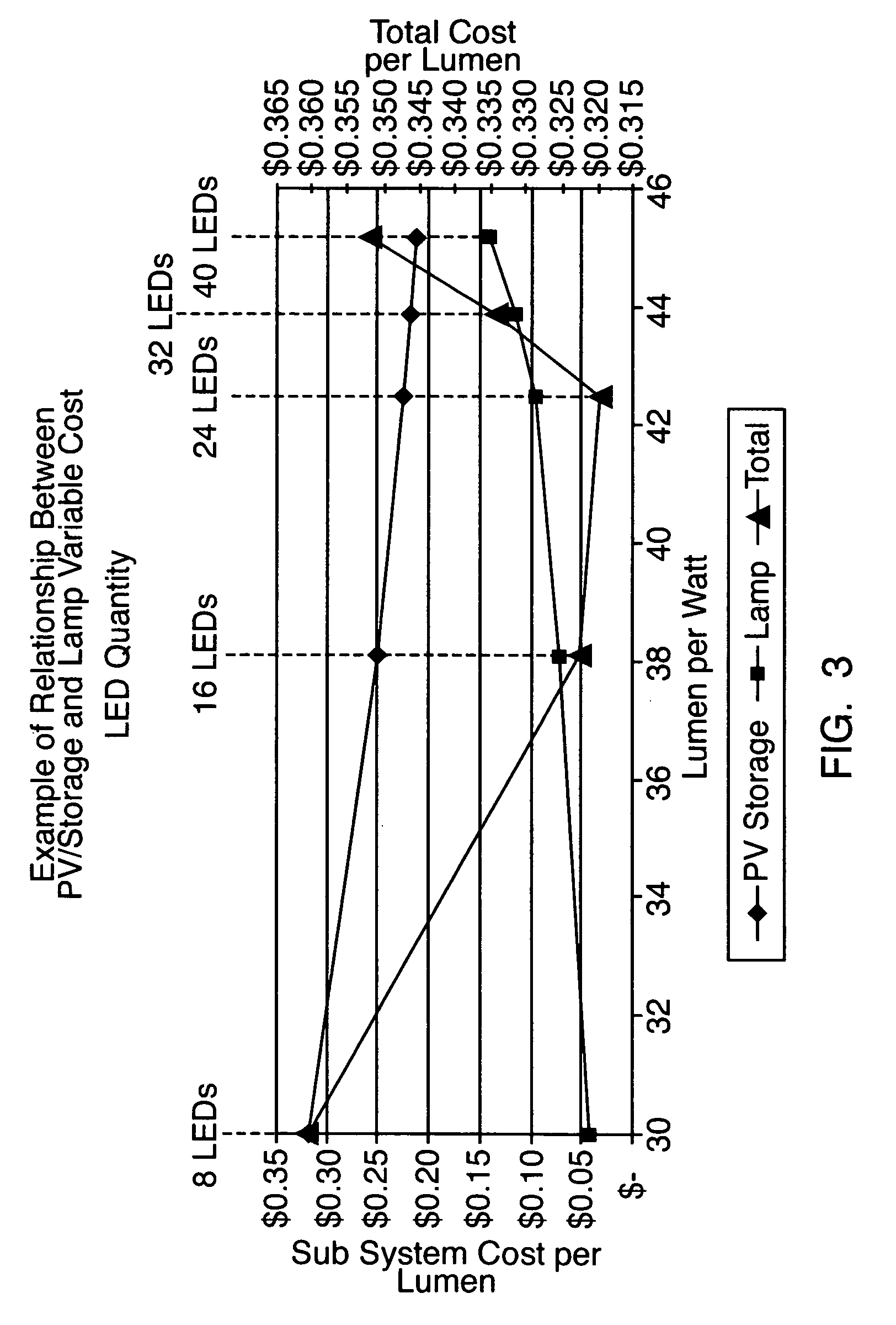
[0039] To optimize the cost of an efficient LED lighting system, the cost of various LED quantities is determined. A useful way to determine the costs of two or more LED quantities is as a variable cost of the LEDs as the quantity of LEDs increases, expressed as a variable cost per lumen. The per lumen variable cost is the total cost of the LEDs divided by the lumens produced the LEDs.

[0040] In practice, LEDs are typically arranged in series strings and additional LEDs are added by including additional series strings. LEDs in lighting systems are typically arranged in series strings based on an optimal system operating voltage. A typical LED can be safely operated (with its maximum current rating) at 3 to 4 volts DC (VDC). Systems considered “low voltage” must not exceed 50 volts anywhere in the system. Furthermore, electronic components rated below 32 VDC often come at a lower cost than components with a higher voltage rating. Under these constraints, an LED string voltage of appr...


PUM


Abstract

A method for optimizing an LED lighting system cost includes steps of determining LED costs, power source costs, and total costs associated with a plurality of LED quantities, and identifying a lowest total cost as an optimal cost. A LED lighting system includes an LED operated by a constant-current driver at less than its maximum current capacity. A programmable controller including a feedback routine is used to compensate for intensity drift as an LED ages. Other embodiments of LED lighting systems include multiple LEDs producing light having various spectrums to optimize the lighting system efficiency and the effectiveness. A charge controller including an MPPT routine is advantageously employed with a LED lighting system powered by a limited-capacity power source.

Description

[0001] The present application claims the benefit of U.S. Provisional Application No. 60 / 640,375, filed on Dec. 30, 2004, the contents of which are herein incorporated by reference in their entirety.FIELD OF THE INVENTION [0002] The present invention relates to light emitting diode (“LED”) lighting systems, and particularly to LED lighting systems intended for use with power sources having a limited storage capacity. BACKGROUND OF THE INVENTION [0003] As energy costs rise and the cost of producing LEDs fall, LED lighting systems are increasingly looked to as a viable alternative to more conventional systems, such as those employing incandescent, fluorescent, and / or metal-halide bulbs. One long-felt drawback of LEDs as a practical lighting means has been the difficulty of obtaining white light from an LED. Two mechanisms have been supplied to cope with this difficulty. First, multiple monochromatic LEDs were used in combinations (such as red, green, and blue) to generate light having...

Claims


Application Information

Patent Timeline
Patent Type & Authority Applications(United States)
IPC IPC(8): G06F9/44
CPCG06Q50/06
Inventor SAYERS, GRAHAMAZZAM, MONEERBERNIER, JOSEPHFOX, MARTINKARLICEK, ROBERT F. JR.LEMONS, THOMAS M.
Owner SOLARONE SOLUTIONS
Why Eureka
Try Eureka