
Positioning signal receiving apparatus

a technology for receiving apparatus and positioning signal, which is applied in the direction of generating/distributing signals, instruments, high-level techniques, etc., can solve the problems of reducing the power consumption effect of intermittent operation and the inability of the apparatus to so as to reduce power consumption and quickly restart the position fixing

Inactive Publication Date: 2006-07-06
FURUNO ELECTRIC CO LTD
View PDF11 Cites 49 Cited by
  • Summary
  • Abstract
  • Description
  • Claims
  • Application Information

AI Technical Summary

Benefits of technology

[0013] Accordingly, it is an object of the invention to solve the aforementioned problems of the prior art and provide a positioning signal receiving apparatus which can be operated intermittently with reduced power consumption and quickly restart position fixing upon restoration of normal operation from sleep conditions.

Problems solved by technology

Therefore, intermittent operation of the positioning signal receiving apparatus is associated with a problem that the apparatus can not quickly restart position fixing after power-on.
If the GPS receiver is operated intermittently by using a temperature-compensated crystal oscillator which oscillates at a high frequency to estimate GPS time with high accuracy immediately after power-on, however, there arises a problem that the GPS receiver draws a large amount of electric current even during the sleep time, thereby diminishing power consumption effect of the intermittent operation.

Method used


Image

  • Positioning signal receiving apparatus
  • Positioning signal receiving apparatus
  • Positioning signal receiving apparatus

Examples


Embodiment Construction

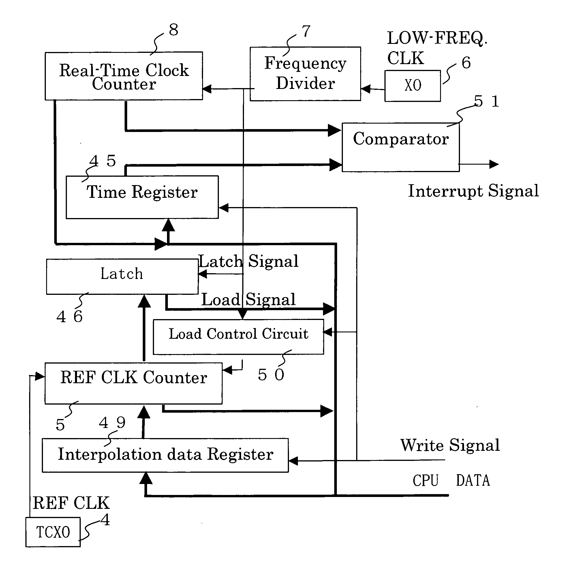
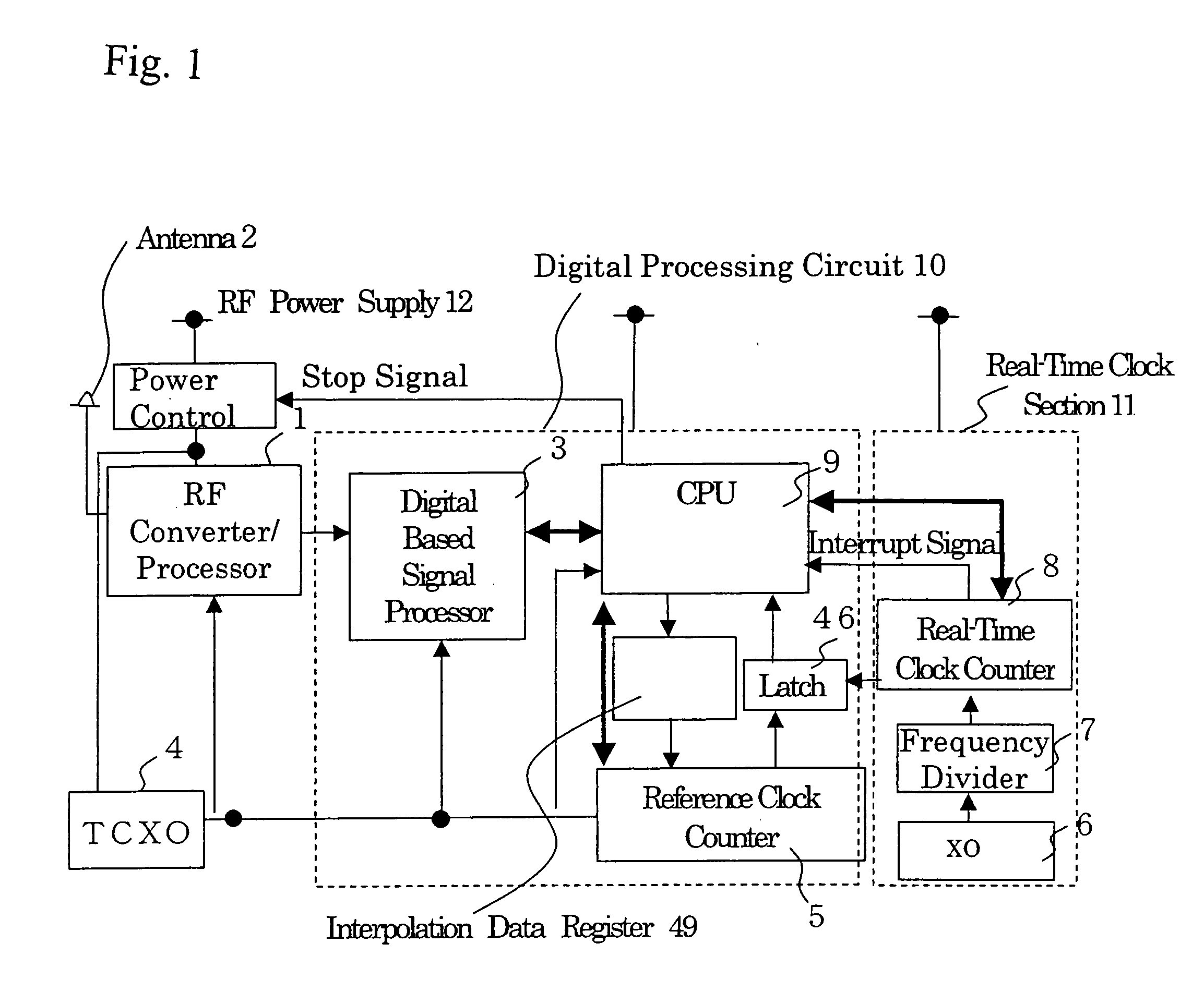
[0036] A GPS receiver according to a preferred embodiment of the invention is now described with reference to the accompanying drawings, of which FIG. 1 is a block diagram of the GPS receiver of the preferred embodiment.

[0037] Referring to FIG. 1, the GPS receiver includes an RF converter / processor 1, an antenna 2, a digital baseband signal processor 3, a temperature-compensated crystal oscillator (TCXO) 4, a reference clock counter 5, a crystal oscillator (XO) 6, a frequency divider 7, a real-time clock (RTC) counter 8 and a CPU 9.

[0038] The RF converter / processor 1 converts a signal received by the antenna 2 into an intermediate frequency (IF) signal and then into a digital signal. The digital baseband signal processor 3 generates information used for detecting C / A code phase and carrier phase by processing this digital signal. The temperature-compensated crystal oscillator 4 serving as a reference clock signal generator generates a 16.3678 MHz reference clock signal and the ref...


PUM


Abstract

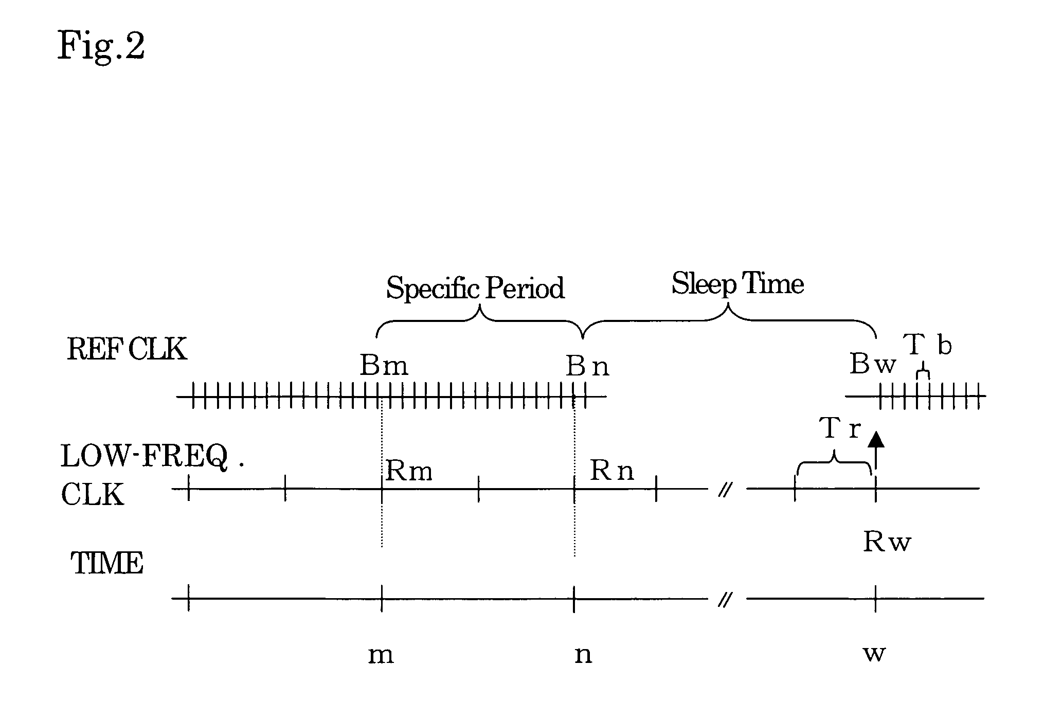
A GPS receiver is alternately switched between sleep conditions under which between sleep conditions under which a temperature-compensated crystal oscillator is shut off for a specific sleep time while a real-time clock section is kept operational and normal operating conditions under which both the temperature-compensated crystal oscillator and the real-time clock section are kept operational. The GPS receiver determines the ratio of the number of pulses of a reference clock signal to the number of pulses of a low-frequency clock signal counted during a specific period of time preceding the sleep time. The GPS receiver estimates a count value which should have been reached by a reference clock counter at the end of the sleep time if the temperature-compensated crystal oscillator continuously generated the reference clock signal based on the number of pulses of the low-frequency clock signal counted during the sleep time.

Description

CROSS REFERENCE OF RELATED APPLICATION [0001] Japanese Patent Application Tokugan No. 2004-368432 is hereby incorporated by reference. BACKGROUND OF THE INVENTION [0002] 1. Field of the Invention [0003] The present invention relates to a positioning signal receiving apparatus for receiving a plurality of positioning signals and determining the location of a point of signal reception. [0004] 2. Description of the Related Art [0005] Conventionally, a positioning signal receiving apparatus, such as a GPS receiver for receiving signals transmitted by the Global Positioning System (GPS), receives radio waves transmitted from a plurality of positioning satellites, obtains GPS time and pseudo-ranges from a point of signal reception to the individual positioning satellites based on the phase of Coarse Acquisition (C / A) code, navigation messages, and so on superimposed on the radio waves, and determines the position of the point of signal reception from the locations of and the pseudo-ranges...

Claims


Application Information

Patent Timeline
IPC IPC(8): G06F1/26G01S19/23G01S19/34
CPCG01S19/23G01S19/34G06F1/04G06F1/3203G06F1/324Y02B60/1217Y02B60/32Y02D10/00Y02D30/50
Inventor YASUMOTO, TAKUJI
Owner FURUNO ELECTRIC CO LTD
Learn More