Transmitting electric power into a bore hole

a technology of electric power transmission and bore hole, which is applied in the direction of electric power transmission ac network, fluid removal, survey, etc., can solve the problems of not being able to pull its own weight, the cable would become so heavy, and the system is not considered suitable for transmitting much higher electric power at the motor voltag

Inactive Publication Date: 2006-07-13
A POWER
View PDF8 Cites 17 Cited by
  • Summary
  • Abstract
  • Description
  • Claims
  • Application Information

AI Technical Summary

Benefits of technology

[0005] According to some embodiments of the invention, the system comprises an electric transmission line extending through the bore hole between an electric power source and a receiving station and voltage converter means for changing the voltage of the electric current supplied to the receiving station, wherein the receiving station includes frequency increasing means for increasing the frequency of the electric current supplied through the electric transmission line, connecting means for supplying the frequency-incre...

Problems solved by technology

This system is not considered suitable of transmitting much higher electric power at the motor voltage, for instance as high as 100 to 400 kW, since that would require very large cross section cable whic...

Method used


Image

  • Transmitting electric power into a bore hole
  • Transmitting electric power into a bore hole
  • Transmitting electric power into a bore hole

Examples


Embodiment Construction

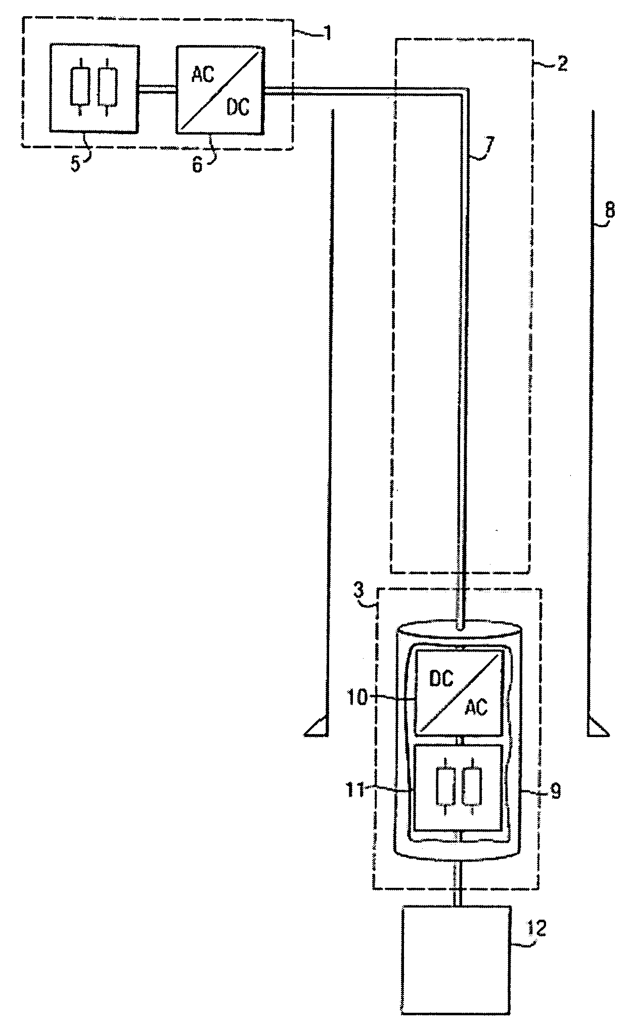
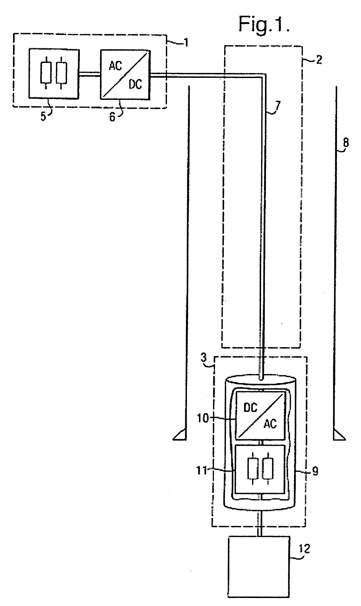
[0012] In the figures, like parts carry identical reference numerals.

[0013] In FIG. 1 a system for transmitting electric power into a bore hole is schematically shown. Elements of the system are grouped in groups (1), (2) and (3), whereby group (1) corresponds to elements associated with the power source, group (2) corresponds to the electric transmission line (2), and group (3) corresponds to elements in the receiver station. The electric power source is connected to the receiving station via an electric transmission cable 7. The bore hole is schematically represented by casing 8.

[0014] The electric power source in FIG. 1, which may typically be located on surface in the case that the bore hole reaches into an earth formation, comprises transformer means 5 for bringing the voltage of the electric current to be transmitted into the bore hole to a desired value, and a converter means 6, here shown in the form of a current rectifier, for lowering the frequency of the electric curren...


PUM


Abstract

A system for transmitting electric power into a bore hole, the system having an electric transmission line extending through the bore hole between an electric power source and a receiving station, wherein the receiving station includes frequency increasing means for increasing the frequency of the electric current supplied through the electric transmission line, voltage converter means for changing the voltage of the electric current supplied to it via the frequency increasing means, connecting means for supplying the frequency-increased electric current to the voltage converter means, and means for connecting an electric load to the receiving station.

Description

PRIORITY CLAIM [0001] The present application claims priority on PCT / EP / 2004 / 05196 filed Jun. 11, 2004.FIELD OF INVENTION [0002] The present invention relates to a system for transmitting electric power into a bore hole. BACKGROUND OF THE INVENTION [0003] Such a system is known and described in paper SPE / IADC 52791 of the Society of Petroleum Engineers, entitled “Electric coiled tubing drilling: a smarter CT drilling system” by D. R. Turner et. al. In the known system, an electrically powered bottom hole assembly is connected to an electric coiled tubing that reaches into a bore hole. The electric coiled tubing holds an electric transmission line, for powering a down hole electric DC motor. The peak power output of this motor is 28 HP, corresponding to some 21 kW. [0004] This system is not considered suitable of transmitting much higher electric power at the motor voltage, for instance as high as 100 to 400 kW, since that would require very large cross section cable which would not ...

Claims


Application Information

Patent Timeline
IPC IPC(8): E21B7/26E21B4/04E21B17/00E21B41/00E21B43/12E21B47/12H02J3/36
CPCE21B4/04E21B17/003E21B41/0085E21B43/128E21B47/12H02J3/36Y02E60/60H02M5/453
Inventor COENEN, JOSEF GUILLAUME CHRISTOFFELTAN BOON KIAT, IVAN
Owner A POWER
Why Eureka
Try Eureka