Thin film coating for fuel injector components

a fuel injector and component technology, applied in the direction of fuel injection apparatus, wear-reducing fuel injection, charge feed system, etc., can solve the problems of fuel injector tip failure or overall performance degradation fuel injector tip failure or other problems, to achieve the effect of reducing the wear of the fuel injector

Inactive Publication Date: 2006-07-13
CATERPILLAR INC
View PDF48 Cites 6 Cited by
  • Summary
  • Abstract
  • Description
  • Claims
  • Application Information

AI Technical Summary

Problems solved by technology

Additionally, the many modern hydraulically actuated and / or electronically controlled fuel injectors often operate in a much more harsh or severe environment, in terms of operating temperatures, pressures, speeds, etc. than conventional fuel injectors.
The decreased surface area of the smaller components in which to spread out the higher contact forces and stresses causes fuel injectors and fuel injector components to experience increased adhesive and abrasive wear at the contact surfaces, such as the nozzle tip and check interface.
The use of low lubricity fuels, in particular, can cause several problems, and most notably fuel injector component wear (both abrasion and adhesion wear), which leads ultimately to the fuel injector tip failure or overall performance degradation of the fuel injector.
Such form of wear is typically caused by lack of lubrication at the interface between two hard surfaces causing a welding or adhesion of the contacting parts, e.g. the exterior surface of the fuel injector needle and interior surface of the fuel injector sliding and impacting against one another without proper lubrication tend to show evidence of severe wear.
These forms or patterns of wear will change the clearance between the exterior surface of the fuel injection needle and the cooperating interior surface of the injector body or guide surface and will make the surfaces rough so the sliding motion of the components will not be smooth, both of which will lead to an incorrect amount of fuel injected into the system.
Eventually, continued wear can lead to failure of the fuel injector tip and / or needle valve.
As indicated above, wear patterns of fuel injector components is particularly evident in fuel injection systems that utilize low lubricity fuels.
A problem encountered with TiN coatings is that a TiN coating is usually applied at extremely high temperatures (e.g. about 450 degrees C.) which may produce unwanted thermal stresses and related failures to the fuel injector components.
It is also believed that TiN coatings on fuel injector needle tend to increase the wear of the needle mating component at the mating or seating location.
In addition, TiN coatings tend to increase the overall cost of the fuel injector needle because the TiN coated fuel injector needle requires tool grade steel to withstand the high temperatures observed in the application of the TiN coating.
Unfortunately, the use of a ceramic material for fuel injector needles is very costly and the resulting monolithic ceramic fuel injector needles have not typically demonstrated the necessary durability or reliability for commercial use in diesel engines or other heavy duty engine applications.

Method used


Image

  • Thin film coating for fuel injector components
  • Thin film coating for fuel injector components
  • Thin film coating for fuel injector components

Examples


examples

[0043] The following Examples will serve to further typify the nature of the invention but should not be construed as a limitation on the scope thereof.

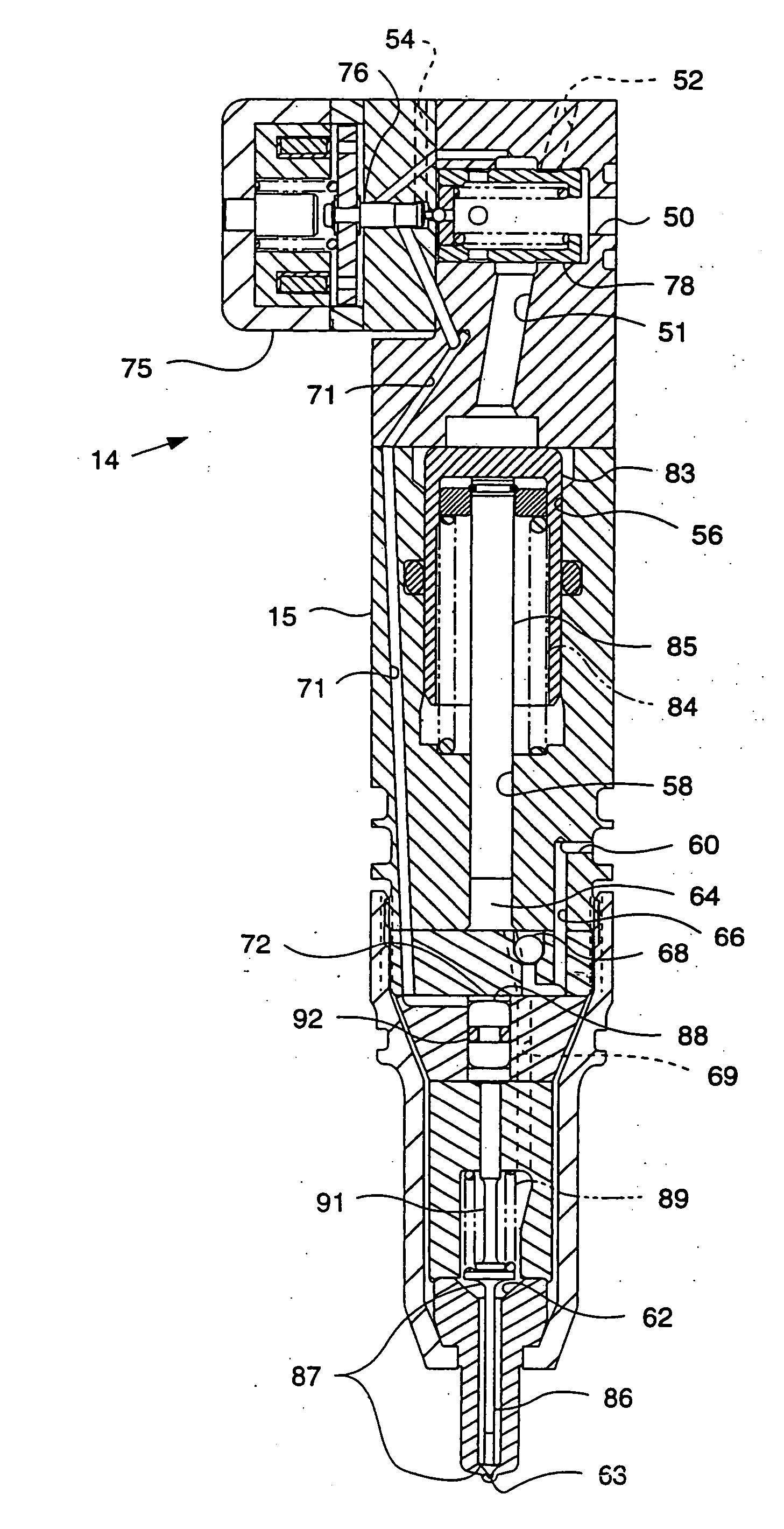
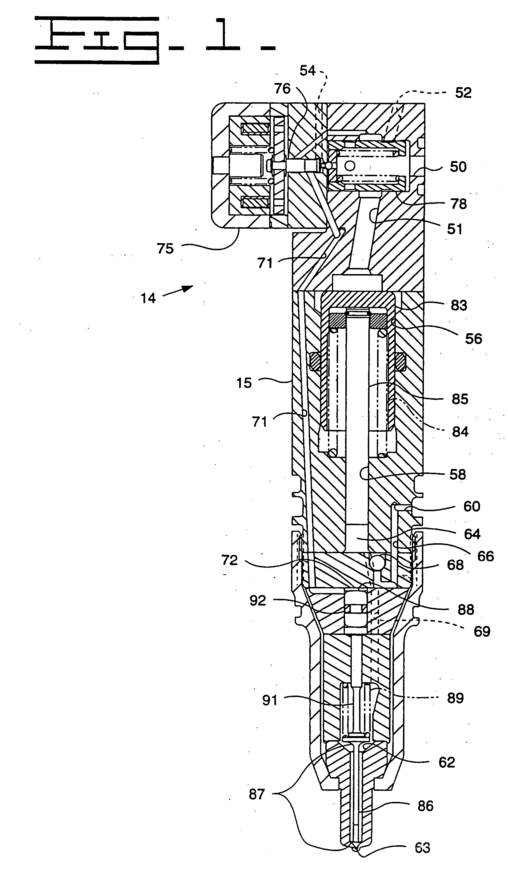
[0044] Accelerated wear tests were performed on Caterpillar fuel injector components operating within a Caterpillar Fuel Injector. The fuel injector needles contained in the tested fuel injectors included at least one with a tungsten carbide containing carbon thin film coating on a low alloy steel substrate (52100 Steel), at least one with a tungsten carbide containing carbon thin film coating on a tool grade steel substrate (M2). The wear test was a combined needle check and corresponding tip wear test that measures the protrusion-change in microns. Generally, the lower protrusion change represents improved wear characteristics. The test samples were compared to wear tests for two baseline Caterpillar fuel injectors having no coatings applied to the needle valve member. The two baseline samples included a needle valve member one ma...


PUM

PropertyMeasurementUnit
thicknessaaaaaaaaaa
thicknessaaaaaaaaaa
thicknessaaaaaaaaaa

Abstract

A thin film coating for a low allow steel or tool steel components in a fuel injector (14), such as a fuel injector needle valve (86) is disclosed. A thin film coating (96) consists of a metal carbon material layer less than 2.0 microns thick applied to a low alloy steel substrate (95) or tool steel substrate (95) used in fuel injector components, such as the fuel injector needle valve (86) or a portion thereof. Optionally, a thin bond layer (98) of chromium is deposited between the steel substrate (95) and the primary metal carbon material coating (96). The thin film coating (96) minimizes abrasive and adhesive wear associated with the needle valve (86) and cooperating nozzle surfaces (62,63) of the fuel injector (14).

Description

FIELD OF THE INVENTION [0001] The present invention relates to thin film coatings for steel components used in fuel injectors, and more particularly for metal carbon material thin film coatings for low alloy steel or tool grade steel fuel injector needles. BACKGROUND OF THE INVENTION [0002] Many internal combustion engines, whether compression ignition or spark ignition engines, are provided with fuel injection systems to satisfy the need for precise and reliable fuel delivery into the combustion chamber of the engine. Such precision and reliability is necessary to address the goals of increasing fuel efficiency, maximizing power output, and controlling emissions or other undesirable by-products of combustion. [0003] In direct injection diesel engine applications, a fuel injector is a precision device that must meter the quantity of fuel required for each cycle of the engine and must develop the high pressure necessary to inject the fuel into the combustion chamber at the correct in...

Claims


Application Information

Patent Timeline
Patent Type & Authority Applications(United States)
IPC IPC(8): F02M47/02F02M61/16
CPCF02M47/027F02M57/025F02M61/10F02M61/166F02M61/168F02M2200/02F02M2200/9038
Inventor SHAFER, SCOTT F.TOMASESKI, JAY E.DAM, CHUONG Q.LONG, MICHAEL C.
Owner CATERPILLAR INC
Why Eureka
Try Eureka